


A full-plastic LED downlight does not solve heat dissipation simply because its visible housing is plastic. Thermal performance depends on drive current, internal interfaces, component placement, housing geometry, ambient temperature and the installed ceiling condition. Evaluate the exact model by tracing heat from the LED and driver to ambient, then measure defined component points under the most restrictive permitted installation.
The practical question is not whether plastic is “good” or “bad” for heat. It is whether the complete design keeps LEDs, driver parts, wiring, polymers, optics and seals within their applicable limits while maintaining the required output.
Define What “Full Plastic” Describes
“Full plastic” is usually a product-family or visible-construction description. It may identify an outer shell, trim, diffuser or major body parts, but it does not disclose the complete internal thermal path. Do not infer a metal spreader, thermally conductive compound, board type or interface material unless the product drawing and bill of materials identify it.
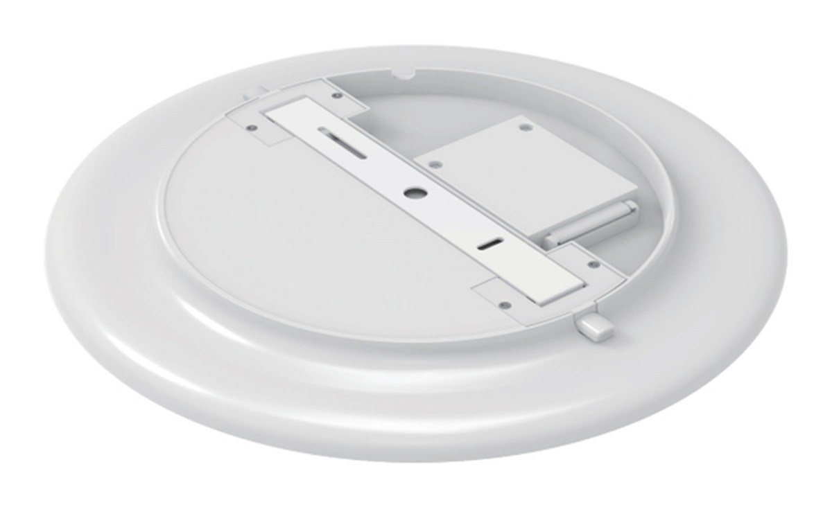
The New Lights legacy HY07 page identifies a full-plastic downlight family and a PC housing entry. That evidence establishes the product form, not the internal heat-transfer mechanism. The current Fixed Diffuser Downlight uses a different die-cast construction, which illustrates why model identity must come before any material comparison.
| Question | Evidence to request | Why it matters |
|---|---|---|
| Which parts are plastic? | Exploded drawing and material list | Separates visible housing from internal thermal components |
| Where are the LEDs and driver? | Board layout, wiring drawing and section view | Locates heat sources and nearby sensitive parts |
| What joins the board to the next layer? | Interface material, contact area and fastening method | Small gaps or poor contact can dominate the thermal path |
| What installation is permitted? | Instructions, insulation-clearance marking and orientation | The ceiling condition changes heat release |
| Which temperature limits apply? | Component data and named measurement points | Prevents comparison with a generic surface-temperature target |
Map the Heat Path Before Measuring
Heat begins at the LED junction and moves through the package, solder connection, circuit board and interfaces. It may then pass through a spreader, structural part or housing before reaching cavity air and the room. The driver creates a separate heat source and can have its own critical temperature point.
DOE thermal guidance identifies drive current, thermal path and ambient temperature as three primary influences on LED junction temperature. That framework is more useful than judging the design by touch or by housing material alone.
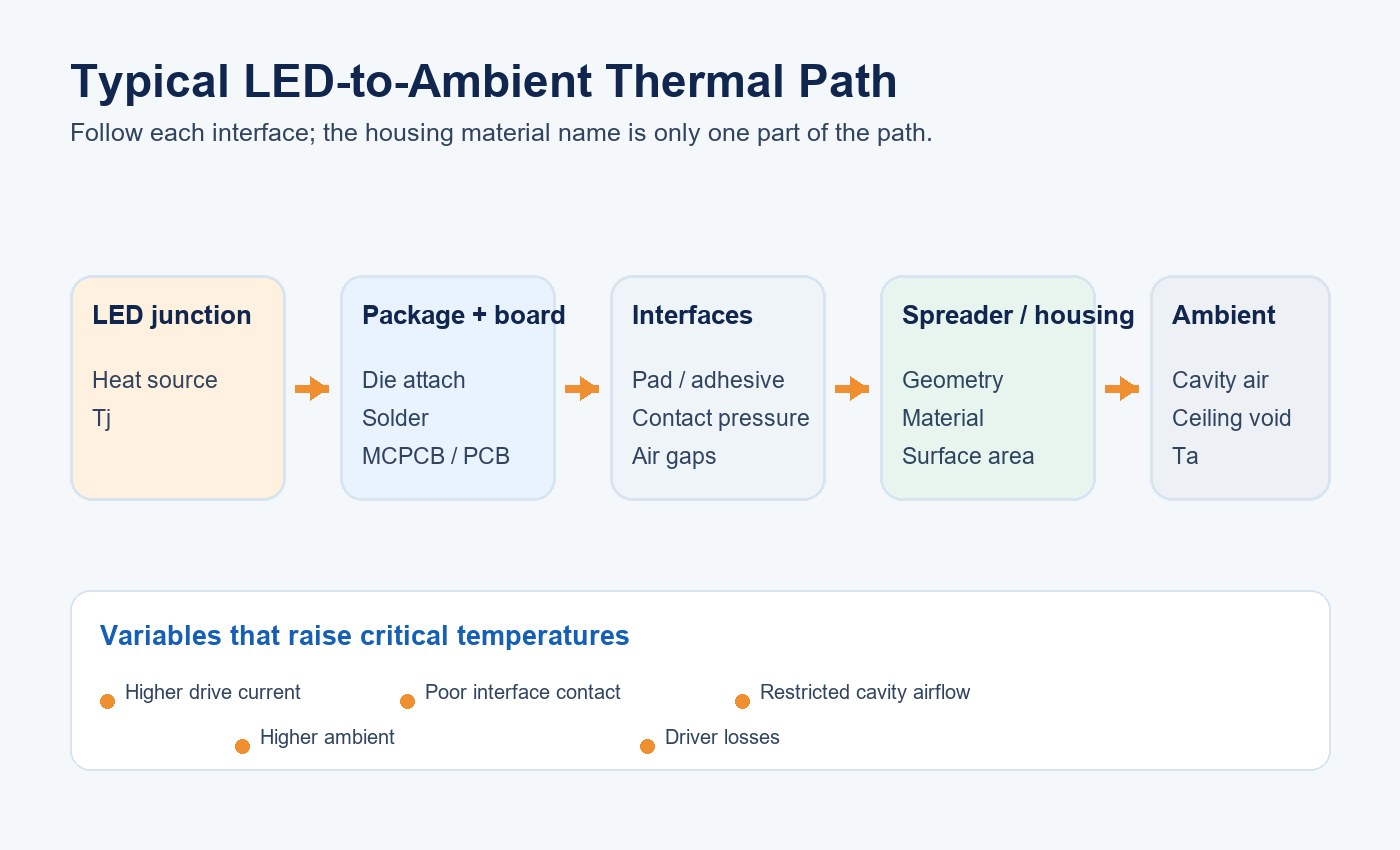
For each layer, record material, thickness, contact area and attachment method. A broad housing surface cannot spread heat effectively if the LED board contacts it through a small, uneven or insulating interface.
Separate Electrical Insulation from Thermal Conduction
Electrical insulation and thermal conduction are different properties. A polymer can provide insulation while resisting heat flow; a filled polymer can improve thermal conduction but may change molding, strength, color, weight or electrical behavior. These properties must be supported by the exact material grade and design.
If a design uses an internal spreader inside a plastic shell, verify its dimensions, isolation and contact path. If it does not, examine how board area, wall thickness, ribs and exposed surface move heat. Avoid adding an assumed metal part to a diagram simply because another downlight uses one.
The SMD and COB LED comparison explains why source format changes heat density and optical geometry. It does not determine the downlight result on its own; package choice must be evaluated within the complete assembly.
Identify Every Heat Source and Sensitive Component
LEDs are not the only source of heat. The driver, dimming electronics, sensor and emergency charging circuit can add losses. A lower LED load does not guarantee a cool driver, especially in a compact sealed cavity.
Map heat sources against electrolytic capacitors, connectors, insulation, adhesives, seals, optical films and polymers. Local hot spots can matter even when the average housing temperature appears moderate.
| Item | Heat or temperature concern | Useful evidence |
|---|---|---|
| LED source | Junction temperature, current density and local heat flux | Source data, drive current and validated board measurement point |
| Driver | Conversion losses and component hot spots | Input/output measurements and driver-case TMP limit |
| Thermal interface | Coverage, pressure, voids and ageing | Drawing, process control and teardown inspection |
| Plastic housing | Material grade, geometry and maximum service temperature | Material specification and measured critical locations |
| Optics and seals | Yellowing, warping, loss of sealing or stress | Material limits and ageing or environmental evidence |
| Wiring and connectors | Insulation temperature and contact heating | Component ratings and abnormal-operation review |
Reproduce the Real Installation Boundary
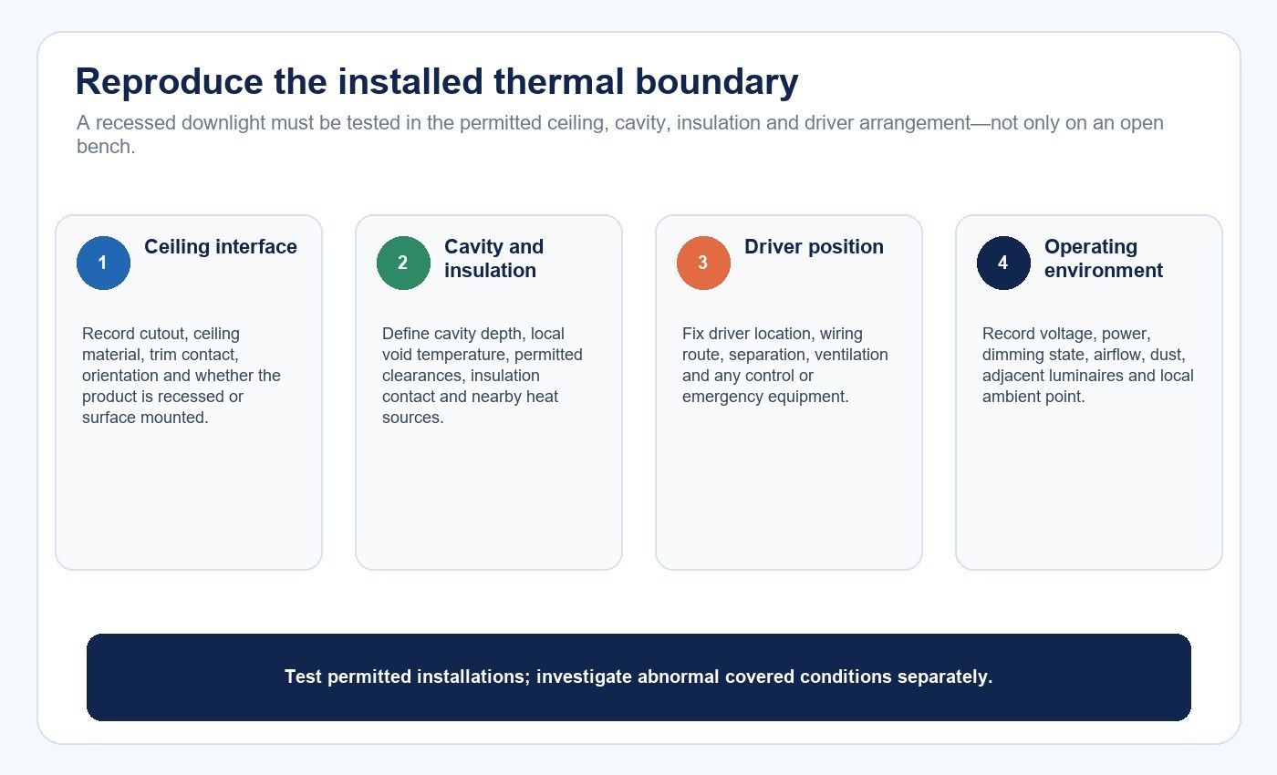
An open-air bench test may understate the temperature of a recessed downlight. Ceiling void temperature, insulation, cavity volume, nearby equipment, dust and air movement change convection and radiation. Closely spaced luminaires can also warm the local environment.
Define whether the product is recessed, surface mounted, insulation-contact rated or required to maintain clearance. Record orientation, ceiling material, cutout, cavity depth and any driver placement outside the body. Test only configurations permitted by the instructions; an unapproved covered condition is a fault investigation, not an acceptance case.
The LED panel downlight installation guide covers electrical isolation, cutout and mounting checks. Thermal validation adds the need to reproduce the cavity and insulation boundary rather than testing the light on an unrestricted table.
Choose Measurement Points That Answer a Decision
A thermal camera helps locate hot regions, but emissivity differences between glossy plastic, painted metal and labels can distort apparent temperature. Use attached sensors at defined component temperature measurement points and document the attachment method.
ANSI/IES LM-98-24 provides a method for measuring in-situ temperatures of solid-state lighting components, including LED-component and driver-case measurement points, test conditions and thermal stability. Apply the relevant product requirements and component guidance to select the actual points.
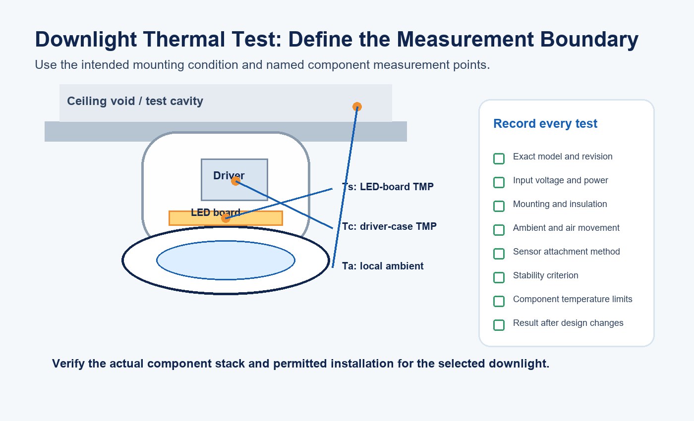
Route sensor wires so they do not lift the board, change contact pressure or create an unintended airflow path. Measure input voltage, input power and operating mode with every temperature run.
Establish Thermal Stability and Worst-Case Operation
Define thermal stability before testing. A fixed elapsed time can be misleading if a high-mass assembly is still warming. Use the applicable test method or a documented rate-of-change criterion, and record the temperature trend rather than one final reading.
Choose the worst permitted operating combination. It may include highest power, warmest CCT channel, maximum ambient, restrictive cavity, dimming electronics, emergency charging or a control state that keeps the driver energized. The worst case must be established from the circuit and installation, not guessed from rated watts.
| Test variable | Minimum record | Comparison rule |
|---|---|---|
| Product identity | Model, revision, LED/driver lot and power setting | Do not combine different revisions as one result |
| Electrical condition | Voltage, frequency, input power, dimming and control state | Compare at equivalent operating states |
| Mounting | Cutout, cavity, insulation, orientation and driver position | Use the permitted installation being approved |
| Environment | Local ambient, room ambient and air movement | Normalize or repeat if conditions differ materially |
| Temperature | Named point, sensor, attachment and time series | Compare with the limit for that exact point |
| Output | Stabilized light output or application measurement | Check whether thermal protection or droop changes performance |
Interpret Temperatures Against Component Limits
A housing that feels cool does not prove a cool LED junction. It can mean the housing is isolated from the heat source. Conversely, a warm housing may indicate that heat is spreading away from the board. Surface touch is not an acceptance method.
Compare each measured point with the applicable limit and correlation. A board temperature can support junction-temperature assessment only when the LED supplier’s method or a validated product correlation connects the two. Apply the same discipline to the driver case and its internal components.
For lifetime statements, use the broader LED thermal management and lifetime validation guide. It separates source lumen maintenance from driver survival, optical degradation and complete-product reliability. A single thermal run cannot establish a complete-luminaire lifetime claim.
Diagnose Symptoms Without Jumping to a Cause
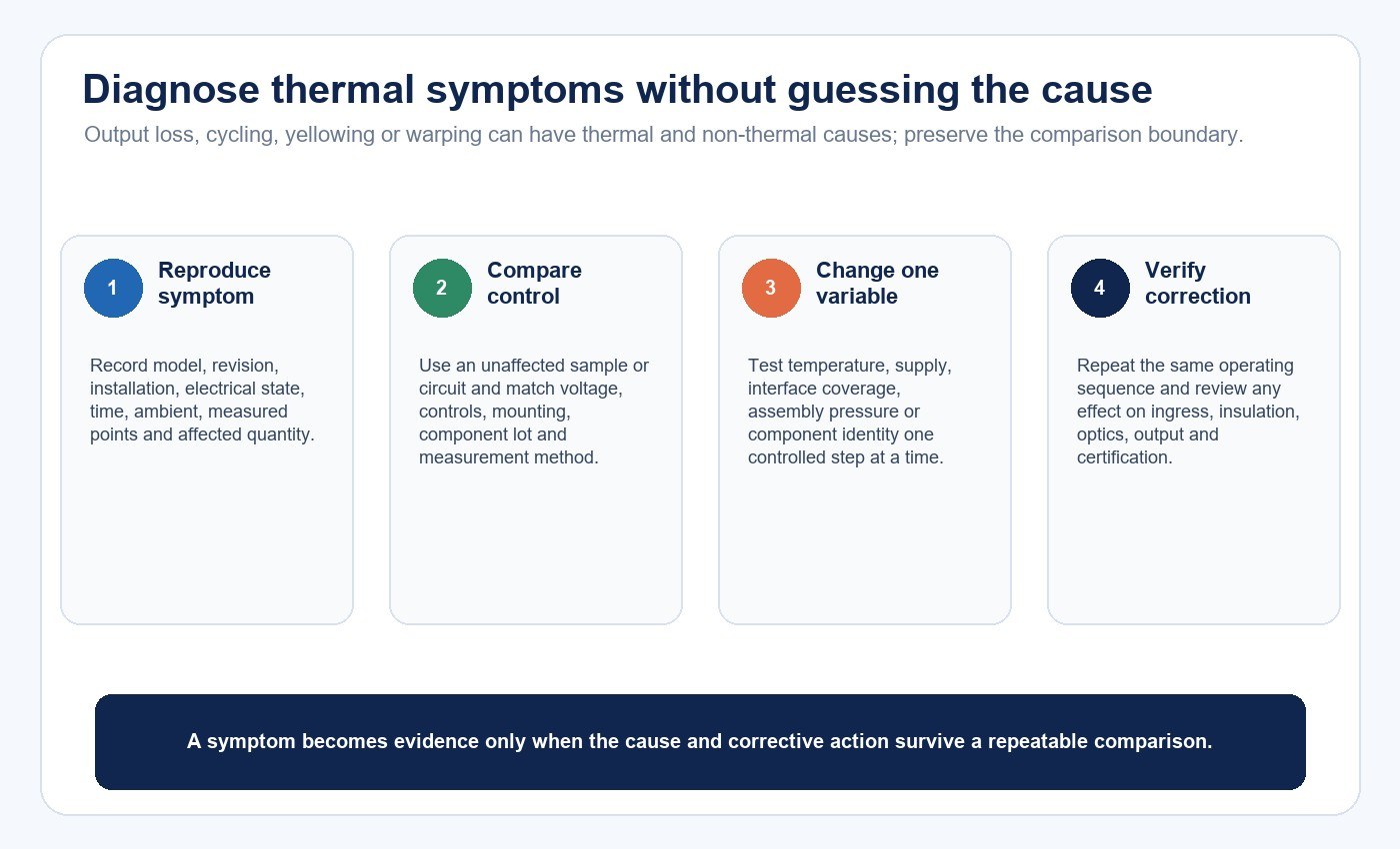
Thermal stress may appear as reduced output, color shift, intermittent shutdown, driver cycling, yellowed optics, warped parts, cracked solder, degraded seals or early failure. None of these symptoms proves one cause.
Compare failing and control samples. Review installation, power, component lot, interface coverage, assembly pressure and temperature history. If the product cycles, determine whether protection is responding to temperature, voltage, load or another fault before changing the housing.
| Symptom | Possible thermal link | Other checks before concluding |
|---|---|---|
| Output falls after warm-up | LED or driver temperature, thermal protection | Dimming signal, voltage and measurement drift |
| Repeated on/off cycling | Driver protection or local hot spot | Supply interruption, sensor logic and loose connection |
| Yellowed diffuser | Optical material temperature or ageing | UV exposure, chemicals, cleaning agents and lot variation |
| Warped plastic | Local temperature, stress or material selection | Molding stress, mounting force and chemical exposure |
| Early driver failure | Elevated component temperature | Surge, input quality, moisture and component quality |
Correct the verified cause, then repeat the same test. Adding ventilation holes, changing resin or reducing current can affect ingress, insulation, output, optics and certification; these are design changes, not isolated fixes.
Control the Thermal Path in Production
Thermal performance can shift with board placement, screw torque, interface thickness, adhesive coverage, resin grade, wall thickness, driver substitution and wiring position. Mark these as critical-to-quality characteristics when the analysis shows they influence temperature.
Use production-representative samples for validation. End-of-line power and function checks can detect some errors, while periodic thermal audits and teardown checks address interface and material variation. Revalidate changes that affect heat sources, heat flow or the permitted installation.
New Lights’ factory and manufacturing capabilities page provides the route for sample control, production coordination and change review. Keep the approved model, bill of materials, drawings and test setup linked to the same revision.
Prepare the Downlight Thermal RFQ
Provide model dimensions, rated input, LED and driver configuration, controls, mounting, cavity, insulation condition, ambient range, duty cycle and destination market. State the required output and any enclosure or ingress requirement separately.
Request an exploded drawing, material grades, component limits, named temperature measurement points, thermal test conditions, output at operating temperature and change-control plan. Ask the supplier to identify exclusions rather than treating an untested installation as accepted.
The ceiling-lighting planning guide helps establish layout and luminaire type before thermal validation. Include maintenance access and spare-part strategy using the lighting maintenance planning guide.
For a defined review, contact New Lights with the exact model, installation drawing, input power, ambient condition, sensor locations and temperature records.
Frequently Asked Questions
Does a full-plastic downlight always need a metal heat sink?
No. The required path depends on source power, geometry, materials, interfaces and ambient conditions. Verify the actual design instead of assuming that a hidden metal part must or must not exist.
Is a cooler outer housing always better?
No. A cool surface can indicate poor heat transfer from an internal hot spot. Judge named component points and the complete thermal path.
Can a thermal camera replace thermocouples?
It is useful for finding hot regions, but emissivity and viewing angle affect readings. Defined contact measurements are normally needed for component-limit decisions.
How long should a downlight thermal test run?
Run until the applicable stability criterion is met, not merely for an arbitrary fixed time. Record the time series, ambient and electrical condition.
Can one test prove the downlight’s rated life?
No. Thermal measurements support a reliability evidence chain, but complete-product lifetime also depends on LED maintenance data, driver and component reliability, materials, cycling and operating conditions.
Editorial Sources
- New Lights, “Full Plastic Downlight – HY07 Model”: https://www.new-lights.com/product/led-ceiling-lamp/full-plastic-downlight-hy07-model.html
- U.S. Department of Energy, “Thermal Management of White LEDs”: https://www1.eere.energy.gov/buildings/publications/pdfs/ssl/thermal_led_feb07_2.pdf
- U.S. Department of Energy, “LED Luminaire Lifetime: Recommendations for Testing and Reporting”: https://www.energy.gov/sites/default/files/2015/01/f19/led_luminaire_lifetime_guide_sept2014.pdf
- Illuminating Engineering Society, “ANSI/IES LM-98-24: Measuring In-Situ Temperature of Solid-State Lighting Components”: https://store.ies.org/product/approved-method-measuring-in-situ-temperature-of-solid-state-lighting-components-in-lamps-and-luminaires/












