


SMD and COB describe different ways of packaging and arranging LED dies, but they are not two complete lamp specifications.
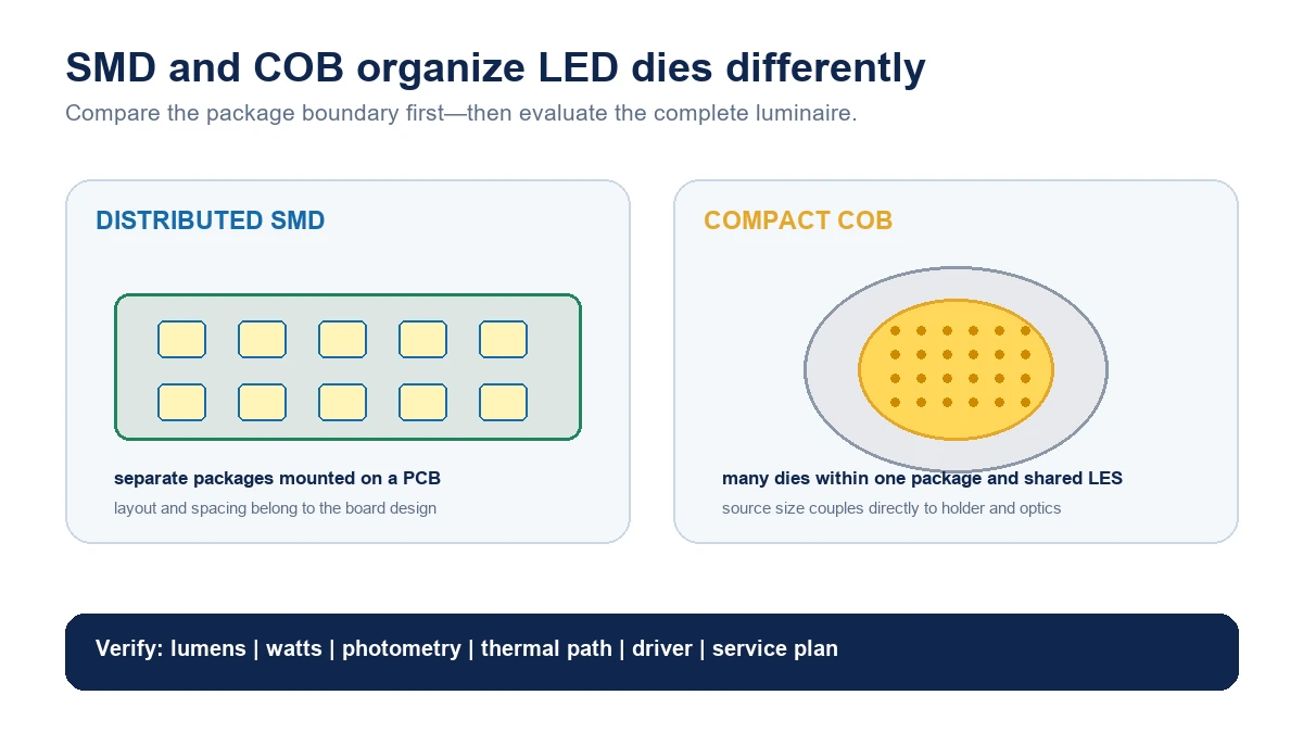
In common lighting use, an SMD design places discrete surface-mount LED packages on a printed circuit board. A COB, or chip-on-board, package integrates many LED dies into one package with a shared light-emitting surface, or LES.
COB can support a compact, high-flux source. A distributed SMD array can spread emitters across a larger board and support flexible layouts. Neither is automatically brighter, cooler, more efficient, longer-lasting or better. Those outcomes depend on the exact LED devices, current, board, heat sink, optics, driver and luminaire construction.
SMD is a broad term
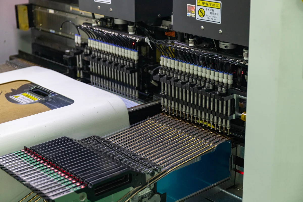
SMD means surface-mount device. In a lighting assembly, packaged LEDs are mounted directly onto the surface of a PCB rather than being installed through holes with long leads.
The label does not identify one package size or performance level. Surface-mount LEDs include different platform classes, such as mid-power and high-power packages, and can vary in:
- die count;
- package dimensions;
- phosphor and encapsulant;
- electrical rating;
- thermal path;
- optical distribution;
- color options;
- lifetime and reliability evidence.
An “SMD bulb” usually means the product uses one or more surface-mounted LED packages. It does not tell the buyer which packages, how hard they are driven or how heat is managed.
What COB means
COB stands for chip on board. DOE describes COB LEDs as packages that can contain many LED dies integrated within one light-emitting surface and powered through a small number of package electrodes. Lumileds similarly describes a COB as one device with many bare dies mounted closely on a substrate beneath a shared phosphor coating.
The dies are mounted and interconnected on a thermally conductive platform, such as a metal-core printed circuit board or ceramic substrate in the DOE study examples. A conversion layer can cover the array to create the required white-light spectrum.
The result is a concentrated luminous surface rather than a board visibly populated with many separate packages. This architecture can support high flux density in a compact form, which is useful when a luminaire needs a single optical source.
COB is still a family, not one product. DOE found variation in substrate, interconnect, die count, LES size and tunable-white architecture among tested commercial COBs.
Architecture comparison
| Decision field | Distributed SMD layout | COB layout |
|---|---|---|
| Source arrangement | Multiple discrete packages placed on a PCB | Many dies integrated in one package and LES |
| Layout freedom | Packages can be spread across different board shapes | LES is concentrated within the COB package footprint |
| Optical interface | Diffuser, lens or reflector can act on multiple source points | One reflector or lens can couple to a compact LES |
| Thermal interface | Heat flows through each package into the PCB and heat sink | High local heat density must move through the COB substrate and heat sink |
| Segmentation | Board can support zones or channels through circuit layout | Fixed or multi-channel COB versions depend on package design |
| Replacement level | Usually the board or module, not individual SMD packages in normal field service | Usually the COB module or luminaire assembly |
| Performance conclusion | Requires exact package, board, current, optics and driver data | Requires exact COB, holder, thermal interface, optics and driver data |
The table describes design tendencies, not guaranteed advantages.
Light-emitting surface and optical control
The physical source size matters to reflector and lens design.
A compact COB LES can work well with a single reflector or lens where a controlled beam is required. The relationship among LES diameter, optic geometry and luminaire aperture affects beam angle, center-beam intensity, field uniformity and glare.
A distributed SMD board can create a broad luminous area directly or feed a diffuser, light guide or array of small optics. This is common in panels, strips, boards and luminaires where the source is intentionally spread across the product.
Do not conclude that COB always produces a narrow beam or SMD always produces diffuse light. A COB can sit behind a wide diffuser, and SMD packages can each use narrow optics. Read the complete luminaire photometry.
Heat: concentration versus distribution
All LED products need a thermal path. The electrical input not converted into light becomes heat that must move from the junction through package materials, board, interface and heat sink to the environment.
A COB can place substantial power into a compact area, making the thermal interface and heat sink critical. DOE notes that COB devices use thermally conductive boards or ceramic substrates to manage heat.
A distributed SMD layout spreads packages across a larger PCB, but this does not automatically make the product cool. Junction temperature still depends on package thermal resistance, board construction, copper layout, current, spacing, interface material, heat sink and ambient conditions.
Compare measured or modeled thermal performance for the actual luminaire. Package type alone is not a temperature reading.
Efficiency and brightness
Brightness is not determined by the letters SMD or COB. Compare complete-product data:
- luminaire lumens;
- input watts;
- efficacy;
- light distribution;
- drive current;
- operating temperature;
- optical losses;
- driver losses.
A high-flux COB can produce a large amount of light from a small LES. A board with many SMD packages can also produce high output. The usable result depends on how much light leaves the luminaire in the required directions.
Avoid comparing an LED package’s laboratory efficacy with a finished lamp’s system efficacy. They represent different boundaries.
Color and tunability
Both architectures can support different CCT, CRI and spectral designs. DOE’s COB study included fixed-CCT and multi-primary tunable-white devices. Distributed SMD boards can likewise use packages with different spectra on separate channels.
Tunable operation requires more than multiple colors. The driver, channel control, thermal balance, optics and calibration all affect the delivered result. Ask for complete-system color data across the operating range.
Color consistency also needs a production plan. Package binning, phosphor, drive current and operating temperature can influence variation. The words SMD and COB do not define a color tolerance.
Reliability is system-specific
DOE has studied different degradation mechanisms across LED package platforms. Its COB research highlights thermal conditions, interconnects, substrate construction, silicone area and moisture as factors worth examining in tested devices.
That does not support a universal lifetime ranking. Complete-luminaire reliability also involves:
- driver components;
- solder joints and connectors;
- PCB and thermal interface;
- optics and seals;
- ambient temperature;
- switching and controls;
- manufacturing process;
- component changes.
Compare rated-life definitions, test evidence, warranty and change-control records for the exact product.
Service and replacement strategy
Neither SMD nor COB normally implies that a field technician will replace individual LED dies. Service typically occurs at the module, board, driver or complete-luminaire level.
Ask:
- Is the LED module replaceable?
- Is the driver separately serviceable?
- Are connectors standardized or proprietary?
- Will replacement modules remain available?
- How is photometric and color matching controlled?
- Does opening the luminaire affect sealing or certification?
A distributed board can be custom to the luminaire. A COB can also require a specific holder, optic and thermal interface. Do not infer serviceability from architecture.
Typical design directions
A distributed SMD approach can suit products needing a large luminous surface, linear form, many zones or close coupling to a diffuser. LED panels are one category where a broad source and diffuser relationship may matter, provided the selected model’s architecture confirms it.
A COB approach can suit compact directional luminaires where a single LES works with a reflector or lens. Buyers can inspect LED downlights and LED spotlights as application categories, then verify the exact source, optic and thermal design for the selected model.
These are design tendencies. Manufacturers can achieve similar application outcomes through different architectures.
A buyer checklist
When comparing products described as SMD or COB, request:
- exact LED package or module identification;
- die and channel architecture at the permitted disclosure level;
- LES or board dimensions;
- drive current and power;
- PCB or substrate construction;
- thermal test conditions;
- complete-luminaire lumens, watts and photometry;
- color and binning data;
- driver and control compatibility;
- lifetime, warranty and change-control evidence;
- module and driver service strategy.
For a product-development discussion, contact New Lights with the target beam, output, form factor, thermal limits, control method and service expectations. Any New Lights-specific architecture must be confirmed against the selected product package.
FAQ
Is COB brighter than SMD?
Not universally. COB can provide high flux density from a compact LES, while an SMD board can combine many packages. Compare complete-product lumens and photometry.
Does COB run hotter?
COB can concentrate heat in a small area, but actual temperatures depend on power, substrate, interface, heat sink and ambient conditions. SMD products also require thermal design.
Is SMD more efficient than COB?
There is no package-name answer. Compare device and complete-luminaire efficacy under defined conditions.
Which is better for spotlights?
A compact COB LES can couple effectively to a reflector or lens, but SMD packages with individual optics can also create controlled beams. Evaluate the target beam and product data.
Which is better for panels or strips?
Distributed SMD layouts often suit broad or linear source areas. The final decision still depends on uniformity, thermal design, optics and system requirements.
Can an SMD or COB LED be replaced?
Field replacement is usually at module, board, driver or luminaire level. Check the product’s service design rather than assuming from the package type.
Which lasts longer?
Neither architecture has a universal advantage. Use model-level lifetime, thermal, driver and change-control evidence.
Editorial sources
- U.S. Department of Energy, “Investigation of the Long-Term Aging Characteristics of Chip-On-Board LEDs: Initial Benchmarks”: https://www.energy.gov/sites/default/files/2021-10/ssl-rti-cob-benchmark-sept2021.pdf
- Lumileds, “Understanding CoB LEDs”: https://lumileds.com/technology/led-technology/understanding-cob-leds/
- Bridgelux, “Introduction to LEDs”: https://www.bridgelux.com/introduction-leds












