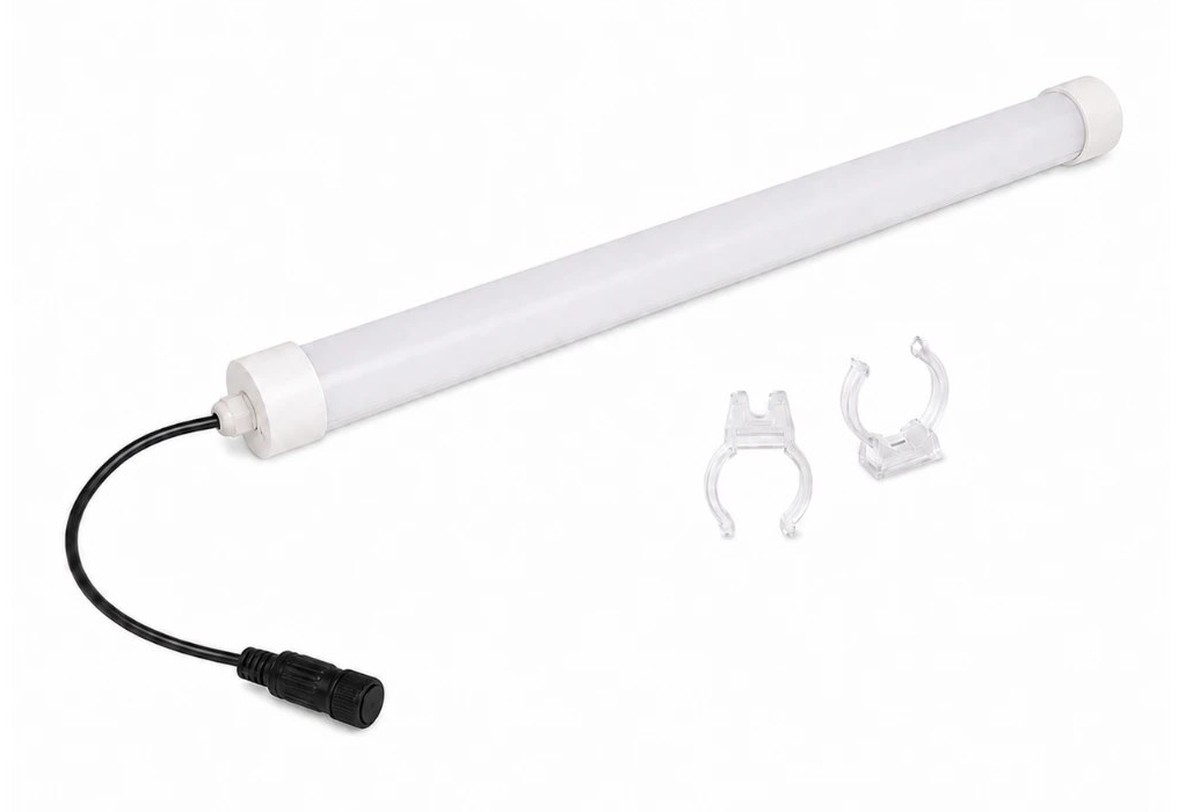
New Lights publishes a T10 LED tube family for fishing-boat and other applications with AC/DC 12–24V input, M10 connectors and an IP65 claim. These features can suit selected auxiliary lighting, but they do not make the tube submersible, saltwater-proof or approved as a navigation, emergency or hazardous-location light.
When a tube flickers, dims or stops operating, diagnose the complete circuit. Boat batteries, chargers, converters, cable runs, connectors, linked loads, mounting and environmental exposure can all contribute.
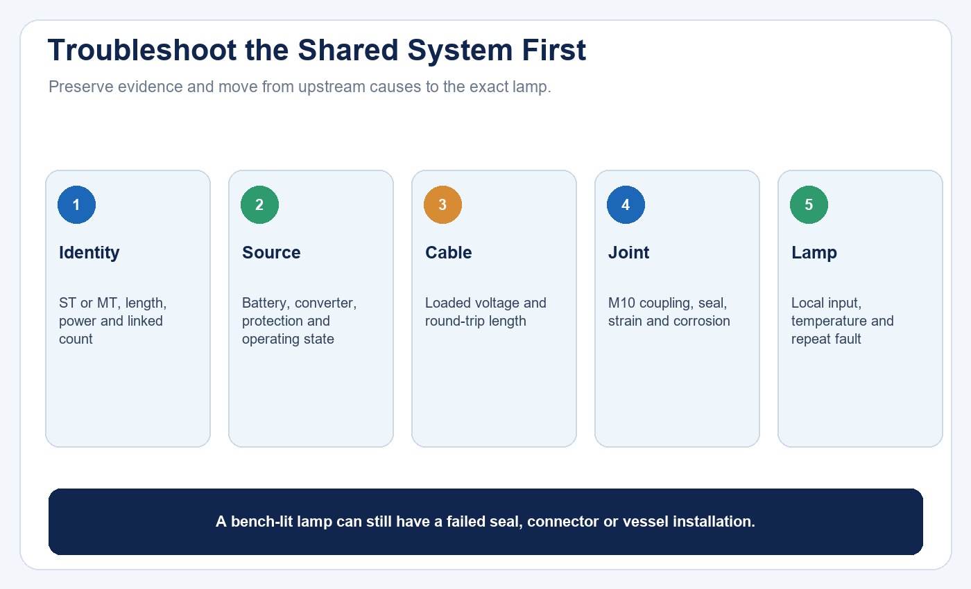
Start with shared system causes before replacing the lamp. Preserve the failed configuration so the evidence is not lost during troubleshooting.
The broader LED failure diagnosis guide explains how to separate supply, driver and LED-board causes. This article applies that logic to the New Lights low-voltage T10 fishing-boat family.
Identify ST and MT Models
The published range includes 350, 550 and 750 mm tubes at 10W, 20W and 30W. Each size appears in an ST and MT version.
The table marks ST models as not interconnectable and MT models as interconnectable. The page says that up to three lamps can be linked. Do not connect an ST product merely because its connector looks similar, and do not exceed the approved linked quantity.
Record the complete model, input arrangement, serial or batch, cable, power source and linked count before troubleshooting.
| Identity field | ST version | MT version | Diagnostic consequence |
|---|---|---|---|
| Published lengths | 350, 550 and 750 mm | 350, 550 and 750 mm | Match physical model before swapping components |
| Published powers | 10, 20 and 30 W | 10, 20 and 30 W | Current and voltage-drop calculations depend on the exact load |
| Interconnection | Not identified as interconnectable | Interconnectable, maximum three lamps | Never build a chain from appearance alone |
| Input family | 12–24 V AC/DC | 12–24 V AC/DC | Obtain exact tolerance, polarity and protection for the model |
Problem 1: No Light
Start with safe checks at the circuit level. Confirm that the supply is available, the correct circuit is selected and protective devices have not operated. Inspect cables and connectors for damage, looseness, contamination or corrosion.
The page states AC/DC 12–24V, but the exact input tolerance, polarity behavior and protection details were not retrieved. Follow the model instruction. Do not assume that every DC polarity or AC source is accepted simply from the range label.
Qualified personnel can verify voltage at approved points under appropriate vessel procedures. A normal reading at the battery does not prove adequate voltage at the last lamp after cable and connector losses.
Record voltage with the circuit loaded, not only open-circuit. Compare the source, first connector and lamp input while the symptom is present. Note whether the charger, engine or other loads were operating, because a fault that appears only in one vessel state may be upstream of the lamp.
Problem 2: Flicker or Intermittent Operation
Flicker can be caused by a loose M10 connector, damaged cable, unstable converter, charger interaction, poor battery connection, voltage drop, internal driver fault or moisture. Note whether the symptom follows engine speed, charging, another load, waves, movement or rain.
Gently observing whether vibration changes the symptom can help locate a mechanical connection issue, but do not pull or twist energized damaged wiring. Isolate power before opening or reseating components according to instructions.
If several lamps flicker together, investigate the shared supply and upstream connections. If only one lamp is affected, compare its connector, cable section and tube with the others while preserving evidence.
Use the flicker, power factor and THD checklist to separate visible symptoms from electrical measurements. On a low-voltage vessel circuit, source and converter stability remain part of the test boundary.
Problem 3: Voltage Drop in Linked Runs
A 12V or 24V circuit can experience meaningful voltage drop across long or undersized cables and multiple connectors. The final lamp may dim, cycle or fail to start even when the source voltage is acceptable.
Calculate the circuit from actual load current, conductor size, round-trip length, connector resistance and source limits. The New Lights page states a maximum of three interconnected lamps, but it does not publish cable-length or current rules in the retrieved content. Obtain those limits before designing a chain.
Do not treat “maximum three” as proof that any three wattages can operate on any adapter or cable. Verify total load and protection.
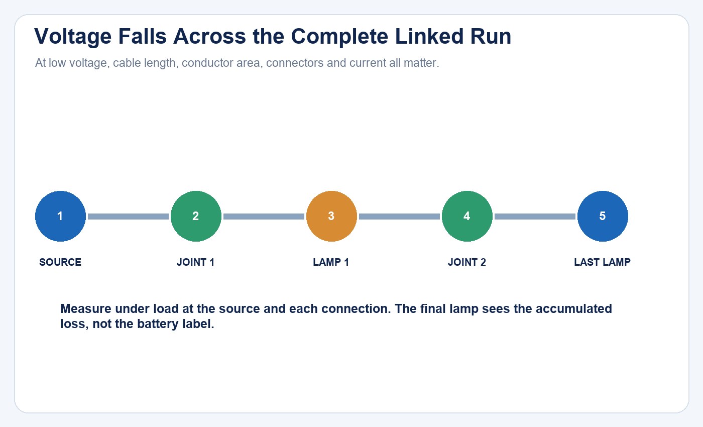
Every cable section and connector adds resistance. Measure the final lamp under load and compare the result with the exact model input limit.
| Observation | Likely boundary | Test that separates causes |
|---|---|---|
| All lamps dim together | Battery, converter or shared feed | Measure source and feed voltage under the same load state |
| Only last lamp cycles | Cable length, connector resistance or chain limit | Measure voltage at each connection under load |
| Fault follows one tube | Lamp or its local connector | Swap only within approved identical configurations and record the result |
| Fault changes with engine or charger | Supply regulation or interference | Compare defined vessel operating states |
Problem 4: Connector Corrosion
Salt, moisture and dissimilar materials can increase contact resistance. Early signs include discoloration, deposits, heat marks, intermittent light or a voltage difference across a connection.
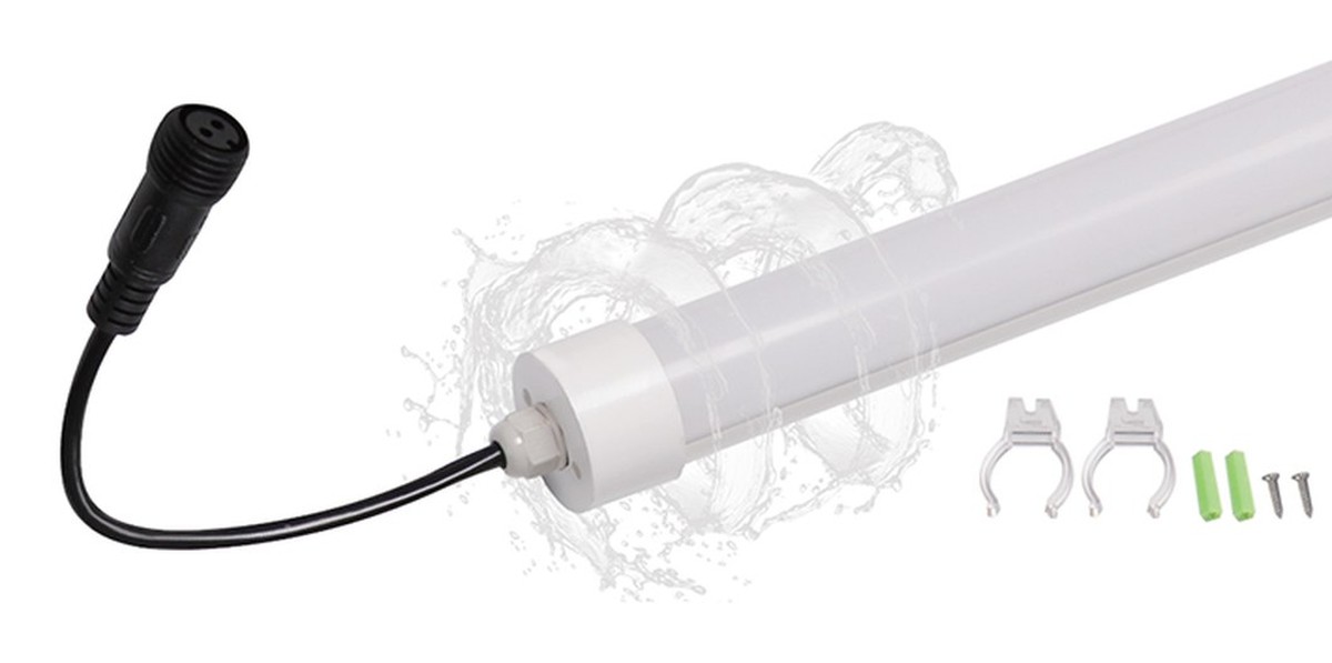
Inspect M10 mating surfaces, seals, cable strain relief and caps. Replace damaged parts with approved components; improvised connectors may change ingress protection and current capacity.
Do not claim corrosion resistance from IP65. IP tests address defined dust and water ingress conditions, not salt-mist durability or galvanic compatibility. A marine or coastal claim needs separate evidence.
The lighting maintenance and spare-parts guide helps structure recurring inspections, approved replacement identities and failure records.
Problem 5: Water Ingress and Condensation
IP65 does not mean immersion protection. Check end caps, connector joints, cable entries, cracks, mounting orientation and evidence of trapped water. Photograph the tube before disassembly and keep the failed configuration for supplier review.
The complete IP report should identify tested model, connectors, caps, cables and orientation. If lamps are interconnected, verify that the linked joint was inside the test scope.
Condensation can occur even without an obvious external leak because temperature and humidity change. IP65 alone does not establish condensation performance.
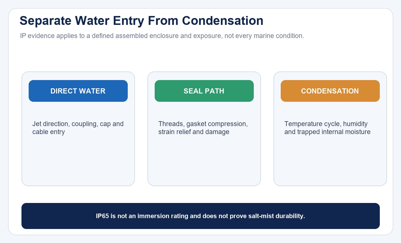
External water entry and internal condensation are different mechanisms. Inspect the complete assembled path and the vessel’s temperature cycle.
| Moisture evidence | Possible mechanism | Required response |
|---|---|---|
| Water near a connector | Loose coupling, damaged seal, cable strain or wrong cap | Isolate, document and replace approved sealing components |
| Droplets distributed inside | Condensation or pressure cycling | Review temperature and humidity cycle and complete-product construction |
| Repeated failure after cleaning | Jet direction, chemical attack or disturbed seals | Check cleaning method and material compatibility |
| Submersion event | Exposure outside the IP65 boundary | Remove from service and follow the responsible inspection procedure |
For a wider explanation of enclosure ratings, use the IP rating guide and the IP65 fixture selection guide.
Problem 6: Vibration and Mounting Damage
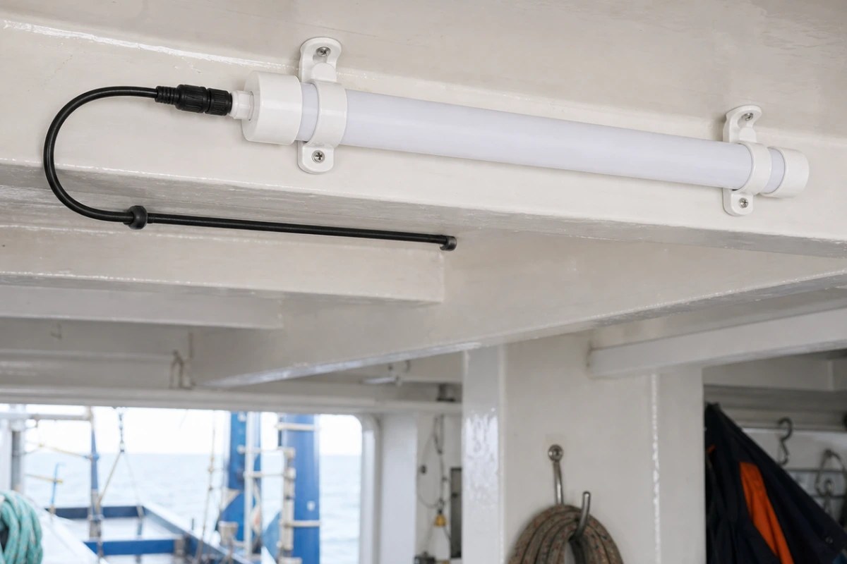
Boat motion can loosen brackets, fatigue cables or load connectors. Over-tightening may also crack plastic parts or distort seals. Use the approved supports, spacing and fastener limits.
Inspect for movement, abrasion, cracked clips and cable tension. The connector should not carry the tube’s mechanical load unless specifically designed to do so.
No vibration or shock report was retrieved for this family, so do not describe it as vibration-resistant without evidence. A rough-service installation may need additional validated retention or a different product.
Problem 7: Reduced Light or Color Change
Reduced output can result from low voltage, dirt, lens aging, high temperature, driver behavior or LED aging. Color change can involve optical materials, LEDs or heat exposure.
Clean only with materials compatible with the tube and seals. Aggressive solvents can haze or crack plastics. Request approved cleaning instructions for fish oils, salt deposits or other site contaminants.
The published table does not provide a reliable efficacy value: the column labelled “Lumen Efficacy” contains interconnection text. Obtain total lumens, efficacy and photometry for the exact model before evaluating performance loss.
Problem 8: Heat Accumulation
Low-voltage LEDs still produce heat. An enclosed compartment, nearby engine equipment, direct sun or restricted airflow can raise the tube and driver temperature.
Request permitted ambient and case-temperature limits. Test the installed tube after stabilization under representative operation. Do not infer high-temperature capability from a low-voltage input or tube shape.
Temperature can also affect cable seals and connector materials. Inspect for hardening, discoloration and loss of elasticity during maintenance.
Keep Safety Functions Separate
Auxiliary tube lighting should not be used as a navigation, collision-avoidance, life-saving, emergency or hazardous-location light unless the exact product carries the required approval and performance evidence.
Color, intensity, distribution, redundancy, power source and placement requirements for regulated vessel lights are not established by a general T10 product page. Maintain required safety lighting independently.
The U.S. Coast Guard warns that unapproved LED, rope, underwater or decorative lighting may violate navigation-light provisions. Treat this tube as auxiliary work lighting unless the exact installation has the approvals and photometric performance required by the vessel’s jurisdiction.
Preventive Inspection Checklist
At intervals suited to the vessel and exposure, inspect:
- Tube model and ST/MT identity.
- Supply, protection and shared loads.
- Cable abrasion, strain and supports.
- M10 connector seating and corrosion.
- End caps, seals, cracks and water evidence.
- Mounting clips and vibration wear.
- Output stability at different operating states.
- Linked quantity and final-lamp behavior.
- Cleaning, UV and heat damage.
- Repeat faults by location and batch.
After service, verify function and the restored protection boundary. A tube that illuminates on a bench may still have a damaged seal or connector.
The LED lighting sample evaluation checklist can be adapted to a representative vessel trial. Include the most exposed mounting positions, longest approved cable run and every intended operating state.
Evidence to Request Before Purchase
Request model-level documentation for:
- input range, polarity and protection;
- wiring and M10 connector ratings;
- allowable linked combinations and cable limits;
- total lumens, efficacy and photometry;
- IP65 complete-test configuration;
- salt-mist, corrosion, UV, vibration and impact where required;
- ambient and case-temperature limits;
- material and cleaning compatibility;
- applicable marine or market compliance;
- service parts and warranty.
| Evidence package | Minimum project question |
|---|---|
| Electrical drawing | What input, polarity, protection, connector and linked combination are approved? |
| IP test record | Which lamp, cable, cap, connector, orientation and conditioning were tested? |
| Environmental evidence | Are salt mist, UV, vibration, impact and cleaning chemicals within scope? |
| Photometric record | Does the work area receive the required output and distribution? |
| Production controls | How will approved materials, sealing parts and wiring remain consistent? |
Use the LED product compliance checklist to map evidence to the target market, and the supplier evaluation guide to control sample-to-production changes. The New Lights factory page provides manufacturing context without replacing model-level evidence.
Conclusion
Common T10 boat-tube problems are best handled by tracing the complete low-voltage system. Identify the ST or MT model, verify supply and voltage drop, inspect M10 connectors and seals, check mounting and environmental exposure, and preserve evidence before replacing parts.
New Lights publishes a six-model 12–24V family. For a bounded review, contact New Lights with the model, supply, linked quantity, cable length, symptom and installation photos.
FAQ
Can an IP65 T10 tube be submerged?
No. IP65 is not an immersion rating. Keep the product within its verified installation scope.
Can all six models be interconnected?
No. The page marks MT models as interconnectable and ST models as not interconnectable.
Why does the last linked lamp flicker?
Possible causes include voltage drop, connector resistance, source limits or an overloaded chain. Verify the approved circuit and measurements.
Does 12–24V mean polarity does not matter?
Not necessarily. Follow the exact model wiring and polarity instructions; they were not shown in the retrieved table.
Is the tube corrosion-resistant in saltwater environments?
That is not proven by IP65. Request salt-mist, material and connector evidence for the intended exposure.
Can it serve as a navigation light?
Not based on the retrieved product page. Regulated navigation lighting requires specific approvals and photometric performance.
Editorial Sources
- New Lights, “IP65 T10 Fishing Boat LED Tubes”: https://new-lights.com/products/led-tube-lights/t8-led-tubes/ip65-t10-led-fishing-boat-tube/
- IEC, “IEC 60529 — Degrees of protection provided by enclosures”: https://webstore.iec.ch/en/publication/2452
- U.S. Coast Guard, “Marine Safety Alert issued for Navigational Lights”: https://www.uscgboating.org/multimedia/news-detail.php?id=512
- UK Maritime and Coastguard Agency, “Marine engineering safety requirements”: https://www.gov.uk/guidance/marine-engineering-safety-requirements