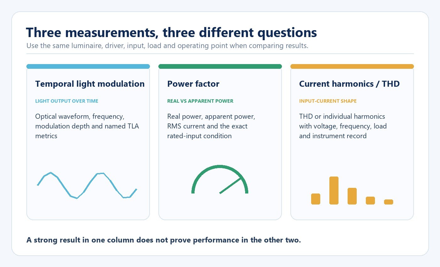
Flicker, power factor and total harmonic distortion describe different parts of LED-system behavior. A high value in one area cannot prove good performance in another. Buyers should request optical-waveform evidence and named temporal-light-artifact metrics separately from power factor, current harmonics, inrush and dimming behavior—and require all results to identify the exact luminaire, driver, input, load, controller and operating point.
The practical task is not to collect the most numbers. It is to make every number reproducible and attach it to the application decision it supports.
Keep the three questions separate
| Measure | What it describes | What the buyer should request |
|---|---|---|
| Temporal light modulation (TLM) | Variation in light output over time | Optical waveform, fundamental frequency, modulation depth, named metric, method and operating point |
| Power factor (PF) | Relationship between real and apparent input power | PF with real power, apparent power, RMS current, voltage, frequency and load |
| Current harmonics / THD | Distortion of the input-current waveform | THD or individual harmonic data with voltage, frequency, load and instrument record |
The U.S. Department of Energy (DOE) describes TLM as rapid variation in light output and explains that LED response follows the current delivered by the driver and dimmer electronics. PF and current harmonics are electrical input measurements; neither describes the optical waveform. A driver can therefore show high PF while the connected LEDs still exhibit substantial modulation, and a low-modulation optical result does not establish acceptable current harmonics.
Specify the complete test configuration
Write the luminaire, lamp and driver model and revision into the request. Add rated input voltage and frequency, supply condition, number of connected units, dimmer or controller model, control protocol, selected power or CCT setting, output level, stabilization time, ambient condition and instrument. If firmware or a programmed curve can change behavior, record that version too.
This configuration record is part of the result, not administrative detail. Driver loading, dimming level and the waveform delivered by a dimmer can change the optical waveform. Power measurements also change with load and input conditions. A waveform screenshot without acquisition settings or a PF value without its electrical conditions cannot support a reliable comparison.
For projects using external controls, the LED driver and dimming compatibility guide explains how to define the complete control chain before samples are compared.
Evaluate temporal behavior through the relevant observation channel
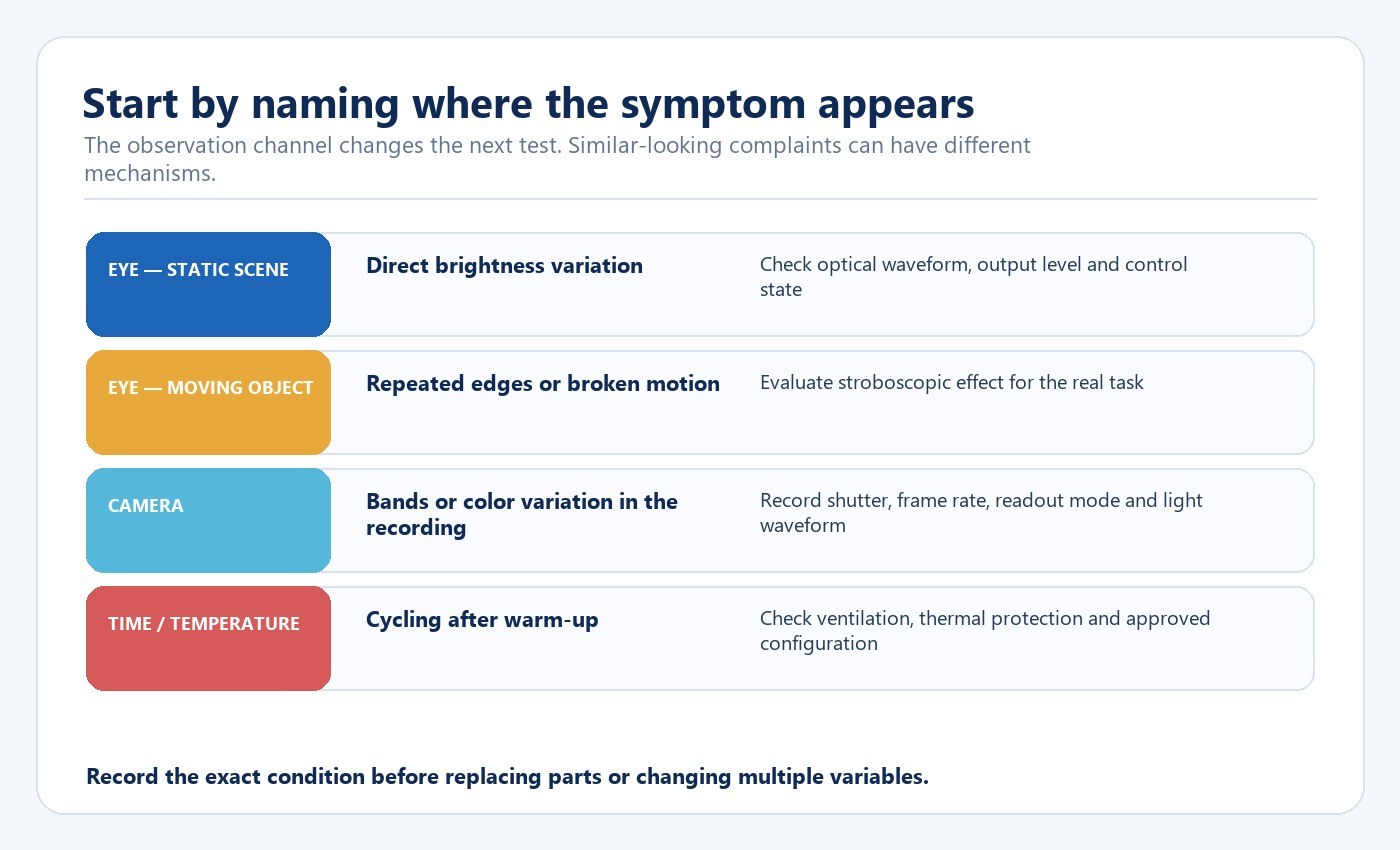
“It flickers” can refer to several different observations. Direct flicker is brightness variation perceived while the observer and scene are relatively still. Stroboscopic effect appears when an illuminated object moves. Phantom-array effects can appear during rapid eye movement. A camera can show bands or color variation because its exposure timing samples different phases of the light waveform.
The DOE notes that no single metric covers all frequencies, observers and applications. PstLM, SVM, waveform measures and application mock-ups answer different questions. The RFQ should therefore identify the occupied task, moving machinery or objects, sensitive users and camera use that matter to the project.
Test every operating point that can change the result
Do not test only at full output. Include the intended minimum dim level, representative intermediate settings, startup, steady operation, control transitions and recovery after power loss. Where the application changes CCT or power settings, treat each relevant combination as a separate operating point.
Low-level instability can arise when the driver changes control strategy, the dimmer-driver pair operates outside a stable range or the connected load falls below a control device’s intended range. Do not assume that pulse-width modulation is automatically unacceptable: frequency, modulation depth, duty cycle, waveform shape and application all affect the outcome. Conversely, a statement such as “high frequency” is incomplete without the actual waveform and test condition.
Read power factor and THD together—but do not merge them
PF can be affected by displacement between voltage and current and by waveform distortion. THD expresses distortion relative to the fundamental component, but a percentage alone does not show absolute current, individual harmonic magnitudes or the effect of many drivers on one circuit.
For circuit review, ask for real power, apparent power, RMS current, PF, THD or individual harmonics and the exact input condition. Add inrush-current evidence and the basis for any units-per-breaker recommendation. The usable quantity depends on the driver, protective device, mains impedance, switching point and number of connected products; simple wattage division is not enough.
Use a controlled troubleshooting sequence
When a symptom already exists, first preserve the original configuration. Record which units change together, whether the issue follows one product, the output level at which it begins, time from startup, ambient condition and any control command. For camera symptoms, also record camera model, shutter type, shutter speed, frame rate, readout or anti-flicker setting and recording mode.
Change one variable at a time. Test an approved known-good unit in the same setup, then—where the manufacturer permits—test the suspect unit with a known-good approved supply or controller. A shared symptom across several luminaires points toward a common supply or control condition; a symptom that follows one unit points toward a unit-level issue. Cycling after warm-up makes thermal conditions and protection behavior a priority.
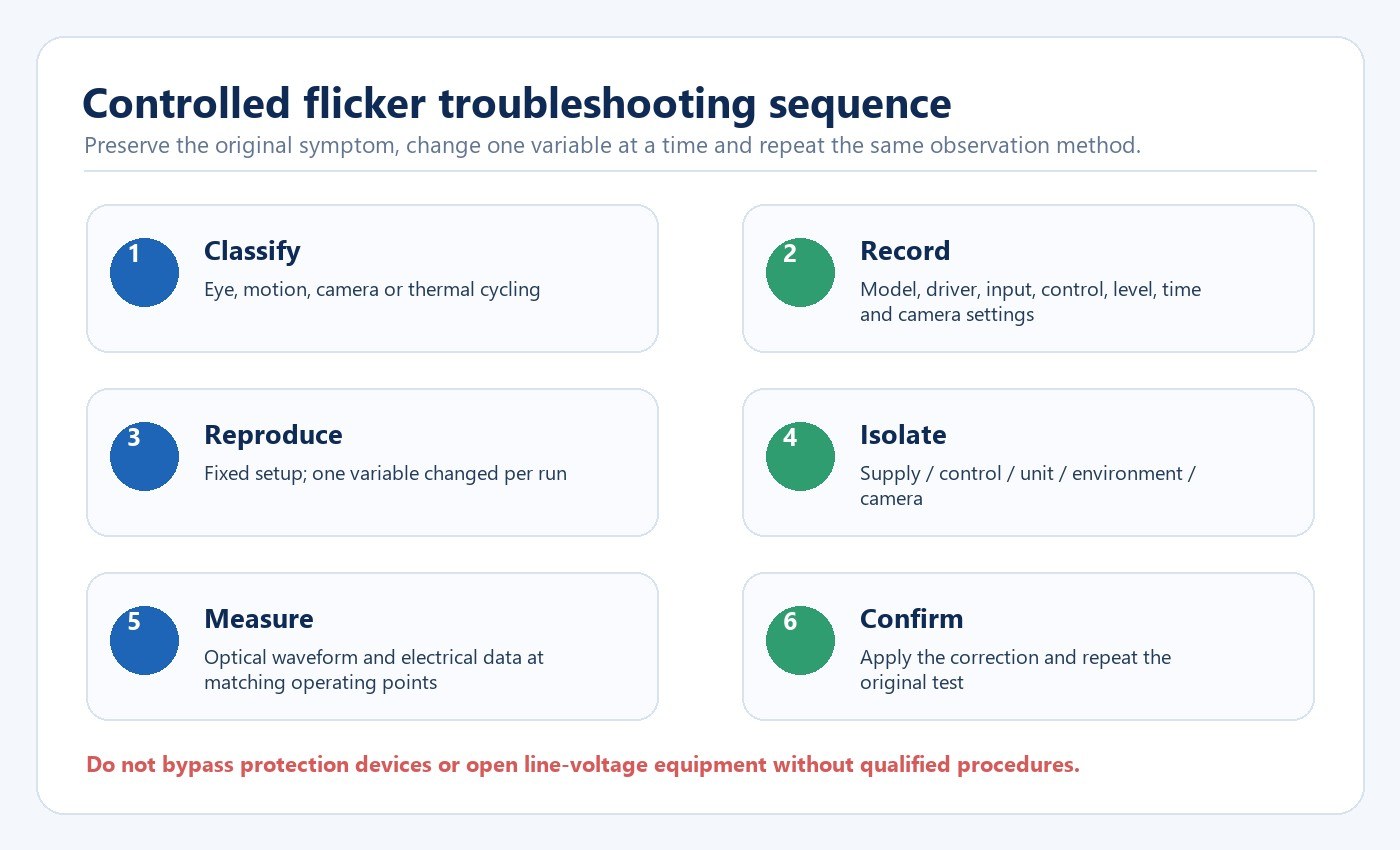
Do not open line-voltage equipment, substitute an unapproved adapter or bypass thermal and protective devices. Internal inspection and electrical measurement require qualified personnel and the approved service procedure.
Treat camera banding as a light–camera interaction
A light can appear steady to the eye and still create bands in a recording. Sony explains that a focal-plane or electronic-shutter system may expose different sensor areas at different moments. If the LED output changes during that readout, rows can record different brightness or color.
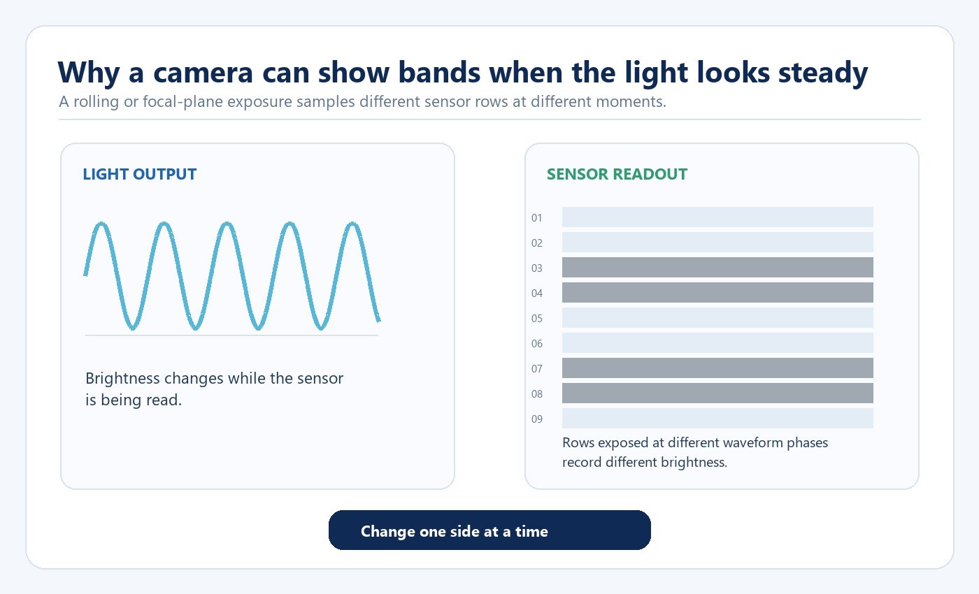
Use the camera manufacturer’s documented anti-flicker or variable-shutter function where available, and inspect the recorded file rather than relying only on live view. A shutter adjustment can reduce captured bands without changing the lamp’s optical waveform. That may solve a production problem, but it does not prove that the light is modulation-free. It can also change motion rendering or exposure, so the corrected camera setting must still suit the intended shot.
Test the control system, not only the luminaire
- Confirm the exact dimmer, controller, sensor, gateway and firmware.
- Build a representative circuit with the intended quantity and wiring arrangement.
- Check startup, on/off cycling, minimum stable level, transitions and power-loss recovery.
- Record optical and electrical measurements at the same operating points.
- Repeat the focused tests after any driver, firmware, controller, load or wiring change.
The New Lights product catalogue provides a bounded product-discovery route when a project needs to identify the exact lamp or luminaire family before requesting driver and control evidence. The Commercial & Retail Lighting Solutions page helps place the measurement plan in an application context. Neither page substitutes for model-level test data.
Build a supplier evidence package that can be compared
| Evidence item | Minimum context | Decision supported |
|---|---|---|
| Optical waveform / named TLA metrics | Model, driver, input, output level, controller, sampling method | Visual, motion and camera-risk screening |
| PF and harmonic record | Rated input, frequency, load, real and apparent power | Circuit and power-quality review |
| Inrush record | Protective device, source impedance, switching condition and unit quantity | Circuit quantity and switching design |
| Dimming / control matrix | Exact controller, load range, firmware, minimum level and transitions | Compatibility and commissioning |
| Change-control record | Driver, firmware, component and supplier revisions | Production consistency and requalification |
For production review, New Lights’ factory and manufacturing capabilities provide the route for discussing sampling and change control. This does not replace the exact test record; it tells the buyer where to attach that record in the approval process.
Buyer comparison checklist
- Exact luminaire, driver, firmware and selectable settings are identified.
- Input voltage, frequency, load, control device and stabilization time are recorded.
- Flicker evidence names its waveform or metric, method and operating point.
- PF and THD come from the same stated electrical configuration.
- Low-level dimming, moving tasks and camera use are represented where relevant.
- Inrush and circuit-quantity recommendations include test conditions.
- Any corrective action is confirmed by repeating the original observation and measurement.
- Driver, firmware, controller or component changes trigger focused requalification.
To review a specific project, contact New Lights with the model list, driver and controller identity, circuit quantity, intended dimming range, camera requirements and available test files.
Frequently Asked Questions
Does high power factor prove low flicker?
No. PF describes electrical input behavior, while TLM describes light output over time. Request both when both affect the project.
Is “flicker-free” a sufficient specification?
No. Ask for the named metric or waveform, measurement method, operating point and exact driver-control configuration.
Why can flicker appear only at low dim levels?
The driver may use a different control strategy, the driver-dimmer pair may become unstable or the connected load may fall outside the control device’s stable range.
Does camera banding prove the light is defective?
No. It shows that the light waveform and camera timing interact under those settings. Compare the intended camera requirement, recorded settings and measured light behavior.
Is a smartphone slow-motion test sufficient?
No. It can reveal a possible light–camera interaction, but it is not a calibrated acceptance measurement.
Can overheating cause periodic dimming or shutdown?
Thermal protection is one possible cause when the symptom follows warm-up. Verify permitted ventilation, orientation and accessories, then use qualified service rather than bypassing protection.
Editorial Sources
- U.S. Department of Energy, “Flicker Research”: https://www.energy.gov/cmei/ssl/flicker-research
- U.S. Department of Energy, “Metrics and Test Methods”: https://www.energy.gov/cmei/ssl/metrics-and-test-methods
- U.S. Department of Energy, “Flicker Basics”: https://www.energy.gov/cmei/ssl/flicker-basics
- Sony, “How to reduce camera flickering”: https://www.sony.com/electronics/support/camcorders-and-video-cameras-hard-drive-camcorders/articles/00122281
- European Commission, “Light Sources”: https://energy-efficient-products.ec.europa.eu/product-list/light-sources_en