


An LED light that does not turn on may have a failed supply path, protection device, driver, control input, connector, LED board or LED package. The fastest reliable approach is not to probe the LEDs first. It is to define the symptom, make the equipment safe, preserve the original condition and isolate the system one block at a time.
This guide is for maintenance, quality and engineering teams. It separates safe field screening from energized electrical tests and laboratory failure analysis. Mains measurements and exposed-circuit work belong to qualified personnel using an approved procedure and equipment rated for the circuit.
First Decide Whether the Product Is Safe to Inspect
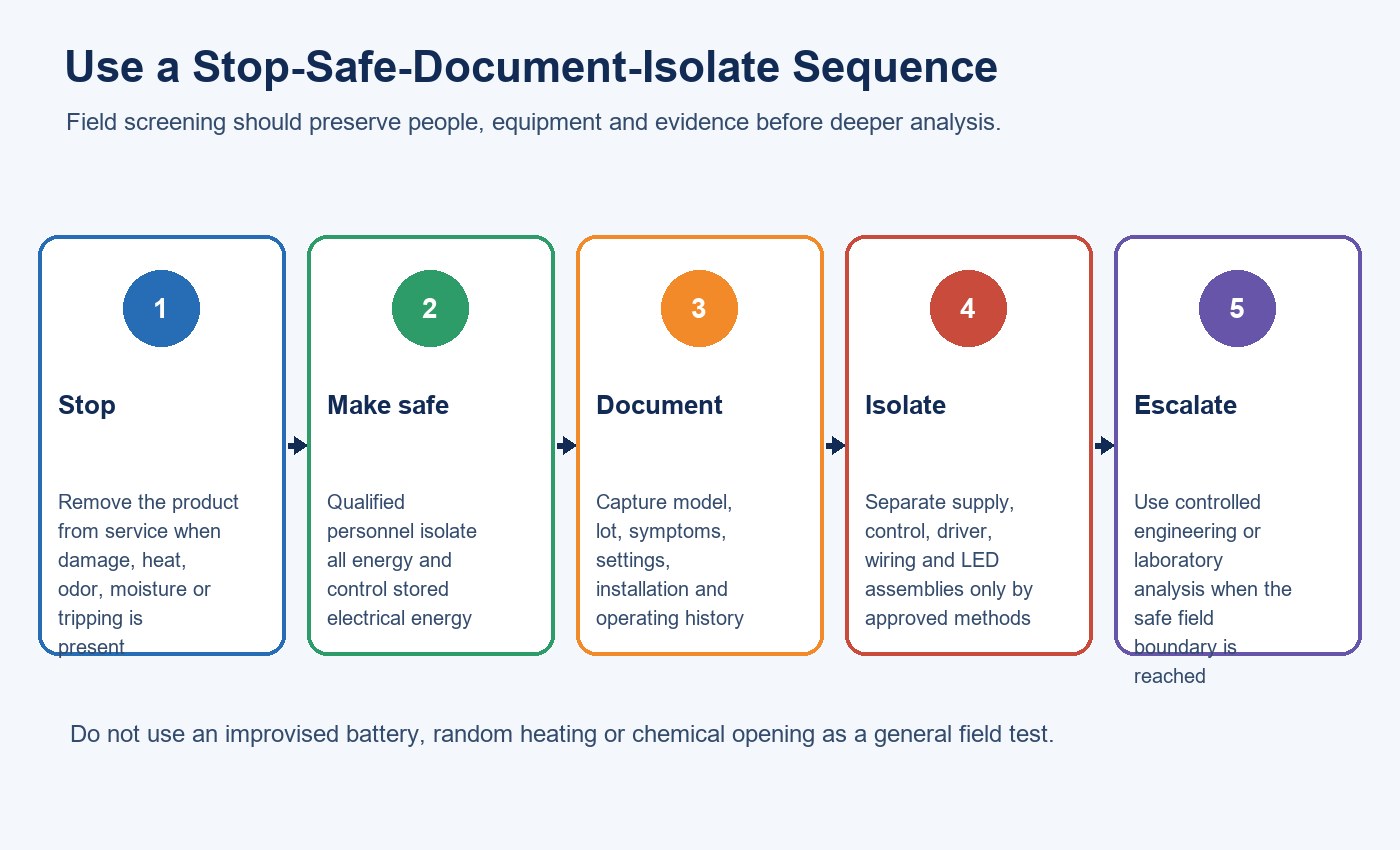
Remove a unit from service when there is smoke, odor, unusual heat, melted material, exposed conductors, water ingress or repeated protective-device tripping. Do not repeatedly re-energize it to reproduce a dramatic symptom. That can enlarge the damage and destroy useful evidence.
Before opening equipment, isolate all energy sources according to the product instructions and the applicable workplace procedure. Stored electrical energy may remain after disconnection. A control cable, emergency supply or battery can also energize part of the system even when the normal branch circuit is off.
Do not use a loose 3 V battery as a universal LED test, randomly heat component leads or attempt chemical decapsulation. LED strings differ in voltage, polarity, current and protection design. Improvised testing can damage the board, mask an intermittent connection or create an electrical and chemical hazard.
Classify the Failure Before Testing Components
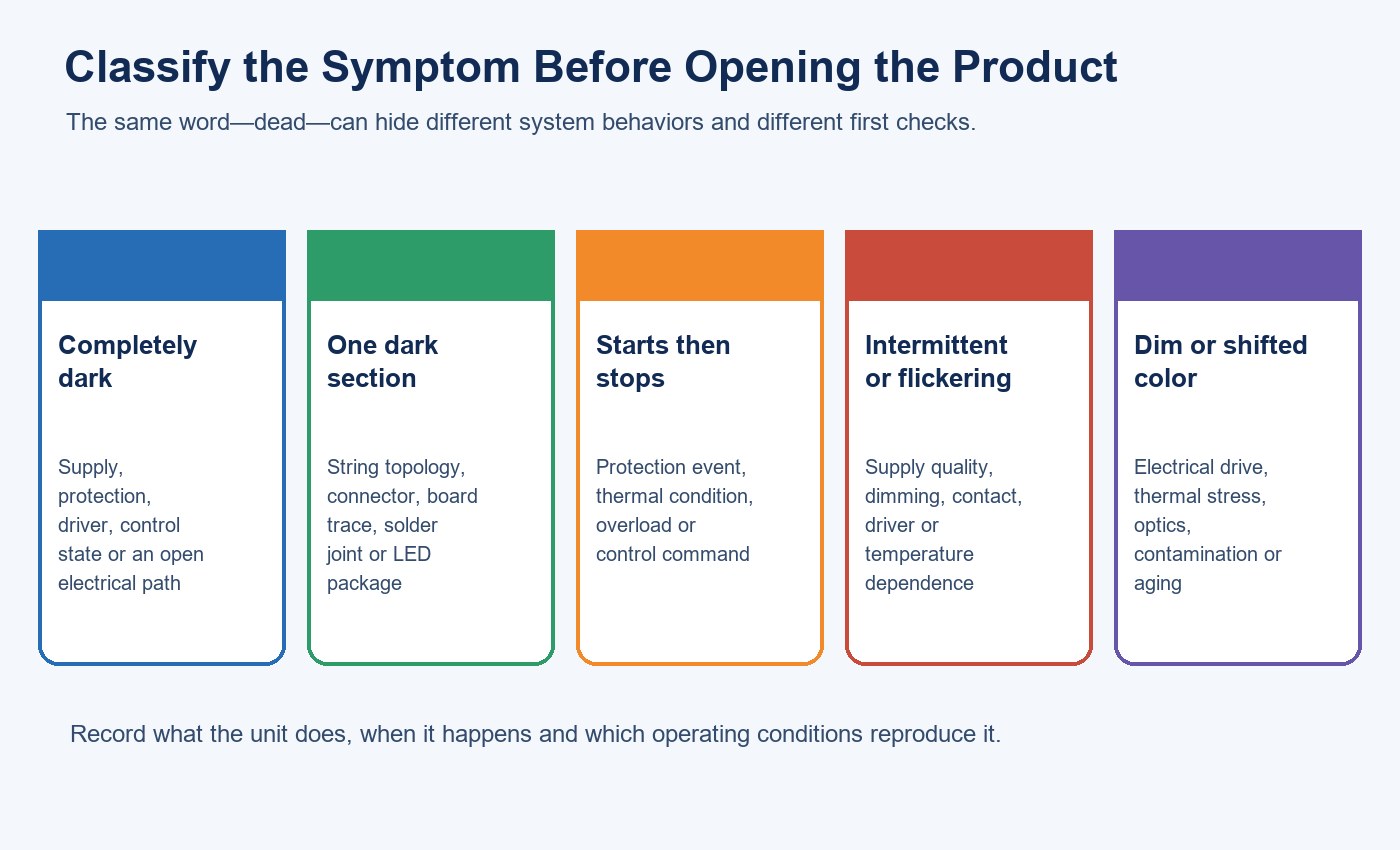
The phrase “dead light” is too broad for a useful report. Describe exactly what the unit does and under which conditions. A completely dark luminaire, one dark section, start-then-stop behavior, intermittent operation, flicker, dim output and color shift are different diagnostic paths.
| Observed symptom | First system blocks to review | Evidence to capture |
|---|---|---|
| Completely dark | Supply, protection, control state, driver input/output, open connection | Circuit state, indicator behavior, model, lot and event history |
| One section dark | Connector, harness, LED-string path, board trace, solder joint | Close photographs and a map of the affected section |
| Starts, then switches off | Driver protection, overload, thermal condition, control command | Time to shutdown, temperature and load/configuration |
| Intermittent or flickering | Supply quality, dimming, loose connection, driver, temperature dependence | Video, dimmer setting, switching state and repeatability |
| Dim output or color shift | Drive current, thermal path, optics, contamination or aging | Baseline comparison, operating hours and optical condition |
The U.S. Department of Energy distinguishes a catastrophic failure, where a luminaire no longer emits light, from degradation outcomes such as excessive lumen loss or color shift. Keeping these modes separate prevents a “still lights” unit from being treated as healthy when it no longer meets the application requirement.
DOE multi-source stress-testing work also treats LED packages, optics, electronics and controls as interacting parts of a lighting system. That is why symptom classification should precede component replacement.
Record Identity, Configuration and Operating History
Record the exact model, serial number or lot, installation date, driver revision, control type and any replacement parts. Add input voltage and frequency, dimming setting, switching schedule, emergency configuration, ambient temperature, enclosure condition and operating hours if available.
Then ask what changed before the symptom appeared: a storm, outage, wiring change, control update, cleaning event, water exposure, relocation, fixture modification or replacement driver. A timing relationship is a lead, not proof. It should guide evidence collection rather than become the conclusion.
For multiple failures, map location, circuit, installation date and lot. Several units on one circuit may point toward supply or control conditions. The same lot failing across independent sites may justify a product investigation. Neither pattern is meaningful without sample identity and the number of units exposed.
Inspect Without Changing the Evidence
With all energy isolated, inspect the housing, lens, cable, plug, socket, terminal, strain relief and ventilation path. Look for impact, cracks, corrosion, water marks, soot, discoloration, loose parts and blocked airflow.
If opening is authorized, photograph the assembly before touching connectors or fasteners. Record the positions of harnesses, protection devices, driver, LED board and thermal interfaces. A disturbed connector or cleaned surface can remove the evidence needed to distinguish installation damage from a production defect.
Isolate Supply, Control, Driver and LED Assemblies
Use the product schematic, approved limits and a known configuration. The aim is to identify the first block where expected behavior disappears—not to replace parts until the lamp happens to light.
1. Confirm the Supply and Protection Path
Qualified personnel should verify the correct circuit, protective-device state, connectors and input conditions. A nominal voltage label does not prove that the required voltage reaches the driver under load. Loose terminals, damaged sockets, incorrect wiring and protection events can all produce a dark luminaire.
2. Confirm the Control State
A healthy power stage may remain off because of a control command, incompatible dimming interface, sensor input, commissioning setting or emergency-mode logic. Record the control state before bypassing anything. If a controlled substitution is allowed, change one variable at a time and restore the original configuration afterward.
3. Separate Driver and Load-Side Evidence
Driver diagnosis requires more than checking whether one component looks damaged. DOE driver-reliability material identifies multiple potential failure points, including protection parts, switching devices, solder joints and dimming circuits. Use an approved test plan to compare input, control state and driver output against the exact product specification.
4. Inspect Wiring, Connectors and the LED Board
An open harness, poor contact, cracked solder joint, damaged board trace or failed LED string can interrupt the load path. Do not assume the visually darkest package started the failure. String topology may cause several LEDs to go dark because of one open path elsewhere.
| Isolation result | What it supports | What it does not prove |
|---|---|---|
| Correct input is present; driver has no specified output | Driver or protection-path investigation | The first failed component or initiating cause |
| Known-good compatible driver restores output | Fault is associated with the original driver path | That every dark unit has the same driver failure |
| Original driver operates a verified compatible load | LED board, wiring or connector investigation | Which package or joint failed |
| Movement changes the symptom | A connection-sensitive fault is plausible | The exact connector, solder joint or crack |
A known-good substitution is useful only when the replacement is electrically and functionally compatible. Match the output range, current regulation, connector polarity, control behavior, protection features and load configuration. If several variables change at once, restored operation cannot identify which change mattered. Record the original and substitute part numbers, test conditions and result, then return to the failed assembly for confirmation. This distinction is important in warranty analysis: swapping a complete driver may identify the affected block, while component-level root cause still requires controlled examination of the original driver.
For related intermittent behavior, use the LED filament bulb flicker diagnosis guide as a separate control-and-driver screening reference.
Treat Intermittent and Thermal Failures as Condition-Dependent
If a product starts cold and fails after warming, record time, ambient temperature, enclosure state and accessible surface-temperature data under the approved method. A thermal protection event, marginal connection, driver component or LED-board condition may be involved. Cooling and restarting the unit only demonstrates repeatability; it does not identify the cause.
Likewise, vibration or movement that changes the symptom points toward a connection-sensitive path but does not prove “cold solder.” Preserve the position and use controlled inspection, imaging or electrical continuity methods appropriate to the assembly.
Teams reviewing early-life and service-life behavior can also use the LED SMD bulb service-life factors guide to separate rated life, thermal stress and complete-product reliability.
Build a Root-Cause Evidence Chain
A repair that restores light proves that the new configuration works. It does not automatically prove why the original unit failed. Root-cause work must connect observation, measurement, hypothesis, confirmation and corrective action.
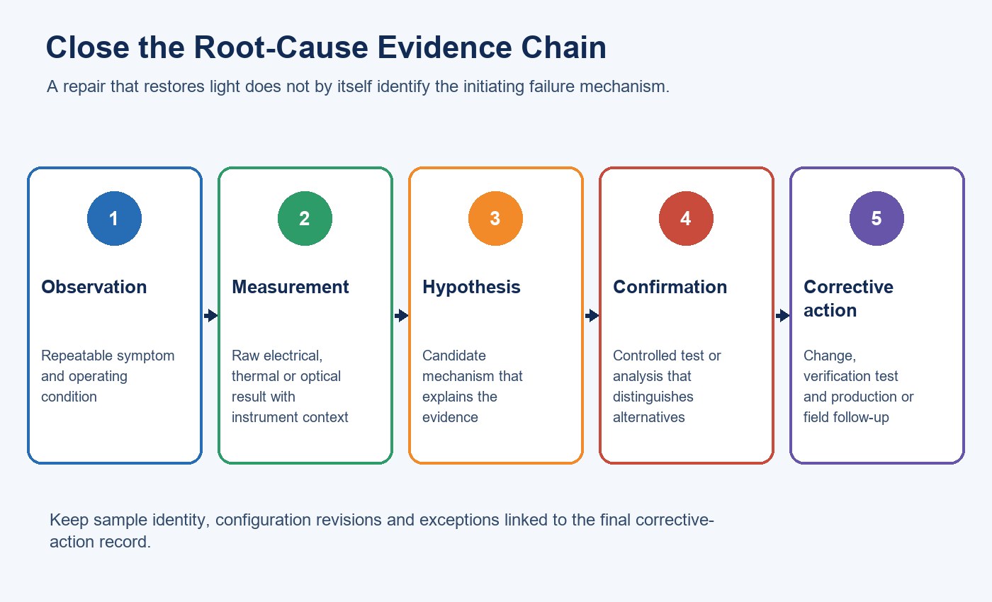
| Evidence level | Example | Decision allowed |
|---|---|---|
| Observation | Unit turns off after 18 minutes | Define the repeatable symptom |
| Measurement | Output stops when a specified driver protection threshold is reached | Narrow the failed system block |
| Hypothesis | Thermal stress may trigger the protection event | Plan a test that separates alternatives |
| Confirmation | Controlled test reproduces the mechanism and excludes competing causes | Assign root cause within the tested scope |
| Corrective-action verification | Revised design passes the relevant test and follow-up sampling | Release or monitor the corrective action |
When reviewing samples, use a repeatable LED lighting sample evaluation checklist so measurements, configuration and acceptance criteria remain comparable. For supplier controls, the LED lighting supplier and factory audit checklist helps connect a confirmed mechanism to process control, change management and traceability.
Prepare a Useful Warranty or Supplier Return
Do not send only a photograph of a dark lamp. Preserve the failed unit and provide a compact evidence package.
| Required record | Minimum useful detail |
|---|---|
| Product identity | Model, driver revision, serial/lot and quantity affected |
| Installation | Circuit, voltage/frequency, control, enclosure and mounting |
| Operating history | Install date, hours/schedule, ambient conditions and recent events |
| Symptom | Exact behavior, timing, repeatability, photos and video |
| Tests performed | Procedure, instrument, limits, raw result and person/role |
| Sample handling | What was opened, moved, replaced or left unchanged |
For application-specific paths, see indoor grow-light troubleshooting or artificial-skylight troubleshooting and maintenance. These pages help separate general electrical failure from system conditions unique to each application.
If a bounded technical review is needed, provide the model, supply, symptom, history, photos, lot information and authorized measurements when you contact New Lights.
Frequently Asked Questions
Does a dark LED luminaire always have failed LED chips?
No. The supply, protection path, driver, controls, connectors, wiring and LED board can produce the same outward symptom. Isolate the system in sequence.
Can I test any LED with a 3 V battery?
No. Voltage, polarity, current, string topology and protection vary. Use only an approved current-limited procedure for the exact package or board.
Does warming a lead prove a bad solder joint?
No. Temperature can change several electrical and mechanical conditions. A response to heat may guide controlled analysis, but it is not confirmation of a solder defect.
How can I distinguish a driver fault from an LED-board fault?
Qualified personnel can compare the exact input, control and output conditions with the specification, then use approved compatible substitution or board-level tests. Record every configuration change.
Is severe dimming a failure?
It can be. Compare measured output and color with the application’s maintained-light requirement and the product baseline. A lamp can remain illuminated but no longer perform its intended task.
What evidence should accompany a warranty return?
Provide product and lot identity, installation and supply details, operating history, symptom timing, photographs, control settings, authorized measurements and a record of any parts changed.
Editorial Sources
- U.S. Department of Energy, “LED Systems Reliability Consortium”: https://www.energy.gov/cmei/ssl/led-systems-reliability-consortium
- U.S. Department of Energy, “An Update on Stress Testing Results for Multi-Source LED Lighting”: https://www.energy.gov/cmei/ssl/articles/update-stress-testing-results-multi-source-led-lighting
- U.S. Department of Energy, “LED Luminaire Lifetime: Recommendations for Testing and Reporting”: https://www.energy.gov/sites/default/files/2015/02/f19/led_luminaire_lifetime_guide_sept2014.pdf
- U.S. Department of Energy, “LED Driver and System Reliability”: https://www.energy.gov/sites/prod/files/2016/02/f29/weeks_reliability_raleigh2016.pdf
- U.S. Occupational Safety and Health Administration, 29 CFR 1910.333: https://www.osha.gov/laws-regs/regulations/standardnumber/1910/1910.333
- U.S. Occupational Safety and Health Administration, 29 CFR 1910.147: https://www.osha.gov/laws-regs/regulations/standardnumber/1910/1910.147












