


LED filament bulb flicker is a system symptom, not a diagnosis. The cause may sit inside the lamp, at the socket, in the supply, or in the interaction between the lamp and a dimmer, sensor or smart control. Describe the symptom, isolate one variable at a time, and measure the optical waveform under the operating conditions that matter.
For procurement, the practical question is not whether a bulb carries a broad “anti-flicker” label. It is whether the exact lamp, control, connected load and operating point produce acceptable temporal light modulation for the intended people, movement and cameras.
Identify the Lamp and Application Before Testing
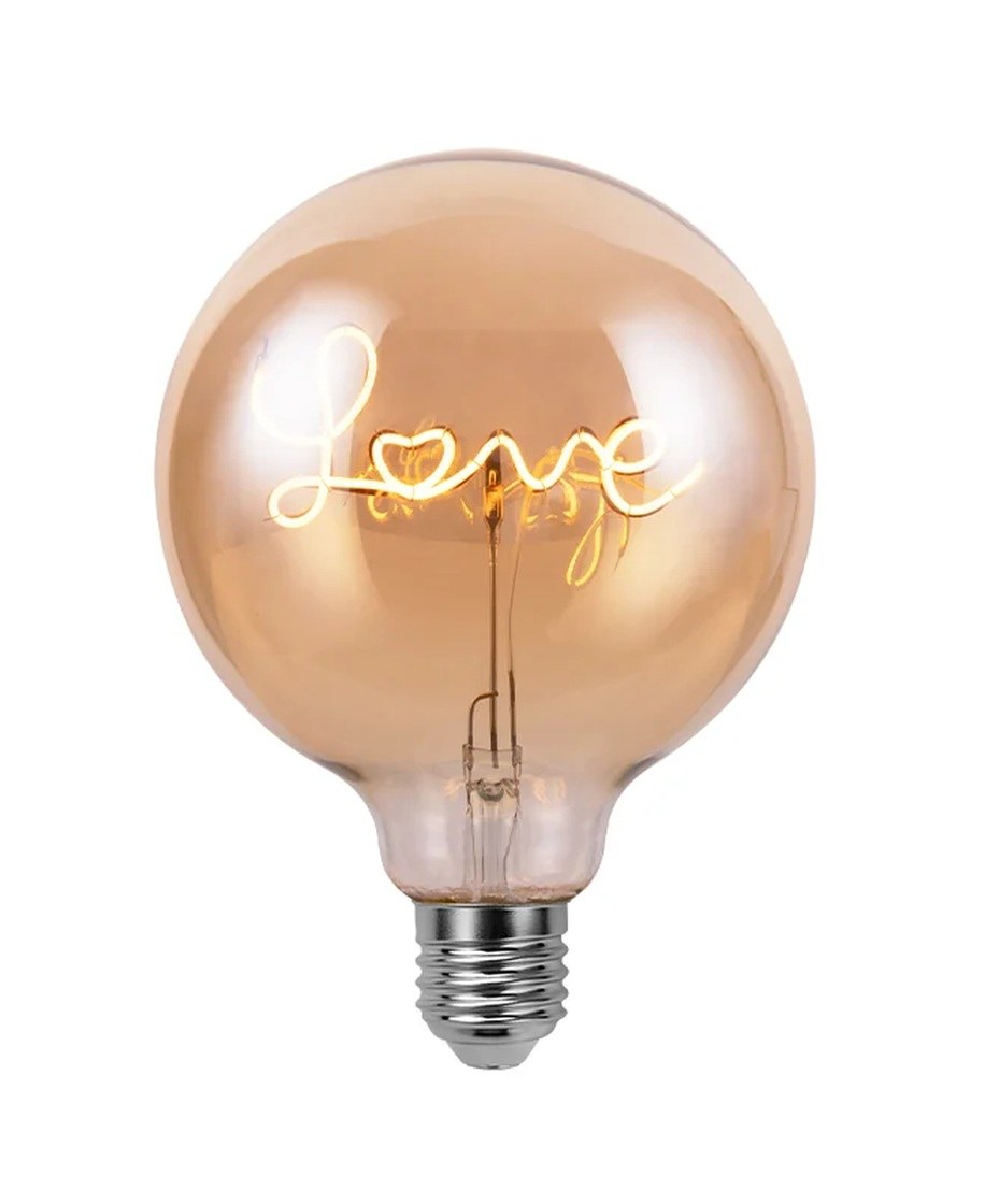
Record the model, base, rated input, dimming status, glass format, filament arrangement and any control restrictions from the current product specification. The New Lights Decorative Letter LED Filament Bulbs use visible filament assemblies to form readable words inside a G125-style decorative globe. The current page presents a LOVE design and customized wording options.
That visual identity does not predict waveform quality or dimmer compatibility. Electrical ratings and test evidence must stay tied to the exact quoted model. For a restaurant, display, hospitality or event project, also record whether the priority is comfortable human viewing, moving-object appearance, video capture, deep dimming, or a combination.
| Record | Minimum detail | Why it changes the result |
|---|---|---|
| Lamp | Exact model, revision, base and sample lot | Similar-looking lamps can use different drivers |
| Supply | Voltage, frequency and circuit condition | The driver responds to the incoming waveform |
| Control | Switch, dimmer, sensor or smart-control model | Controls can change conduction and minimum load |
| Connected load | Number of lamps and total load | Some controls are unstable at low loads |
| Operating point | Full output, intermediate points and minimum stable level | Flicker may appear only at one setting |
| Application | Human viewing, motion or camera settings | Acceptance metrics and observations differ |
Describe the Symptom Instead of Writing “It Flickers”
Different temporal effects call for different tests. Direct flicker is visible modulation when the observer and scene are relatively still. A stroboscopic effect becomes apparent when an illuminated object moves. A phantom-array effect may appear during rapid eye movement. A camera can show rolling bands even when a person sees steady light.
Also distinguish regular modulation from intermittent flashing. A repeating shimmer at a particular dimmer position suggests a control or driver interaction. Random dropouts may point to a loose contact, failing component, unstable supply or control reset. A symptom that appears only after warm-up adds temperature and component drift to the test conditions.
| Observation | Record with it | First diagnostic direction |
|---|---|---|
| Visible pulsing at full output | Warm-up time and supply condition | Lamp driver, supply or connection |
| Shimmer only while dimmed | Dimmer model, load and setting | Compatibility and minimum-load interaction |
| Dark bands on video | Frame rate, shutter and dimmer setting | Camera-waveform interaction |
| Flash when another load switches | Other load and switching event | Circuit disturbance or control behavior |
| Intermittent dropout after warm-up | Time, temperature and socket condition | Connection, component or thermal behavior |
Understand the Driver–Current–Light Chain
LED filaments respond rapidly to changes in current. The internal electronics convert the incoming supply into current for the filament strings. Rectification, energy storage, regulation and dimming behavior determine how much current varies over each cycle. Light output follows those variations closely enough that waveform shape, frequency, modulation depth and duty cycle can all matter.
This is why filament appearance, glass clarity and rated wattage cannot establish flicker performance. It is also why a lamp that is acceptable on a plain switch can behave differently on a phase-cut dimmer. The LED filament bulb driver selection guide covers the electrical design choices; this article focuses on diagnosing the installed lamp-control system.
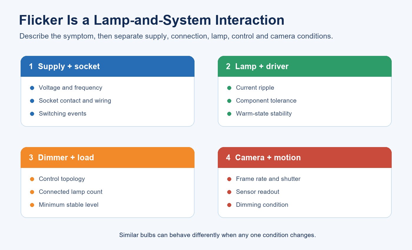
Separate Four Cause Groups
Supply and connection conditions
A loose socket contact, damaged lampholder, unstable supply, poor neutral connection or intermittent switch can cause flashing. Isolate power before inspection and use a qualified person for wiring checks. Stop using a holder that is discolored, arcing, unusually hot or mechanically damaged.
Lamp and driver behavior
The internal circuit may allow current ripple, become unstable outside its intended input range or contain a fault. If the symptom follows one lamp to a known-good compatible switched circuit, compare a second verified sample from the same configuration. One failed unit does not prove lot-wide behavior, but it does justify containment and further sampling.
Dimmer and control interaction
Phase-cut dimmers alter the input waveform. Their behavior also depends on connected load and control setting. A low-wattage lamp or small group may sit below the stable range of an older dimmer. Some combinations are steady at full output but shimmer, step, drop out or flash near minimum. The filament LED bulb dimming guide explains why “dimmable” must be paired with an approved control and load range.
Camera interaction
Camera banding depends on the light waveform plus frame rate, shutter speed, exposure and sensor readout. A lamp may look steady to a person but band on video, or appear acceptable with one camera setting and fail with another. Video acceptance therefore needs a defined camera test rather than a universal “camera-safe” promise.
Use a Safe Isolation Sequence
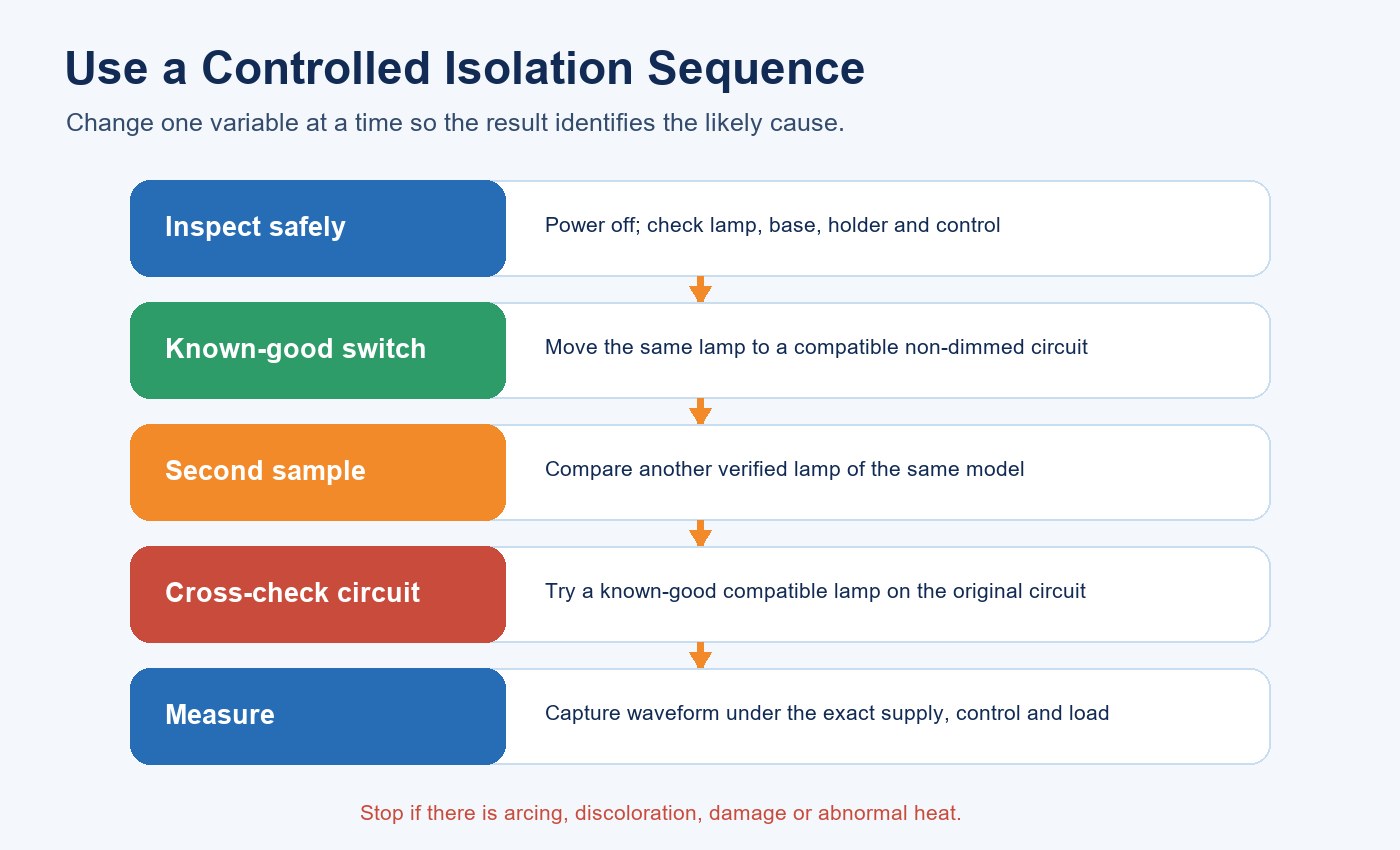
Begin with the simplest known-good condition. Confirm the lamp rating and inspect the base and socket with power isolated. Test the suspect lamp on a known-good switched circuit that matches its rating. Then compare a second verified sample. Finally, test a known-good compatible lamp on the original circuit. Change only one variable at each step.
| Test step | Keep constant | Change | Interpretation |
|---|---|---|---|
| Baseline | Original lamp and circuit | Nothing; document symptom | Establishes a repeatable starting condition |
| Known-good switched circuit | Same suspect lamp | Circuit and control | Improvement points toward installation interaction |
| Second verified sample | Same known-good circuit | Lamp sample | Difference points toward sample variation or defect |
| Known-good compatible lamp | Original circuit | Lamp | Repeated symptom points toward circuit or control |
| Dimmer sweep | Lamp, dimmer and load | Output setting only | Locates unstable operating regions |
For a basic consumer symptom sequence, see why a spiral-style LED bulb may flicker. For procurement, continue beyond symptom isolation and capture repeatable measurements.
Test the Dimmer Across the Real Load Range
Record the dimmer manufacturer, model, control type and stated load range. Test the actual number of lamps expected in the project, not only a convenient laboratory load. At minimum, observe full output, representative intermediate points and the lowest stable level after warm-up. Repeat switching and dimming transitions because start-up and steady-state behavior are different conditions.
If several circuit sizes are planned, test the minimum and maximum connected loads. A result from ten lamps does not establish one-lamp performance. Likewise, a lamp that starts at one dimmer setting may still shimmer after the control settles. The approval record should name acceptable and excluded combinations rather than implying universal compatibility.
Use a Phone Camera for Screening, Not Acceptance
A phone can reveal obvious bands or pulsing and can compare two samples when settings are held constant. Automatic exposure and rolling shutter can also exaggerate, hide or reshape the artifact. Lock exposure when possible, use the same frame rate and shutter, keep distance and background constant, and record the settings.
A positive phone observation is a reason to investigate. A clean clip is not proof that modulation is absent. The broader flicker, power factor and THD buyer checklist explains why these electrical and optical characteristics cannot substitute for one another.
Measure the Optical Waveform
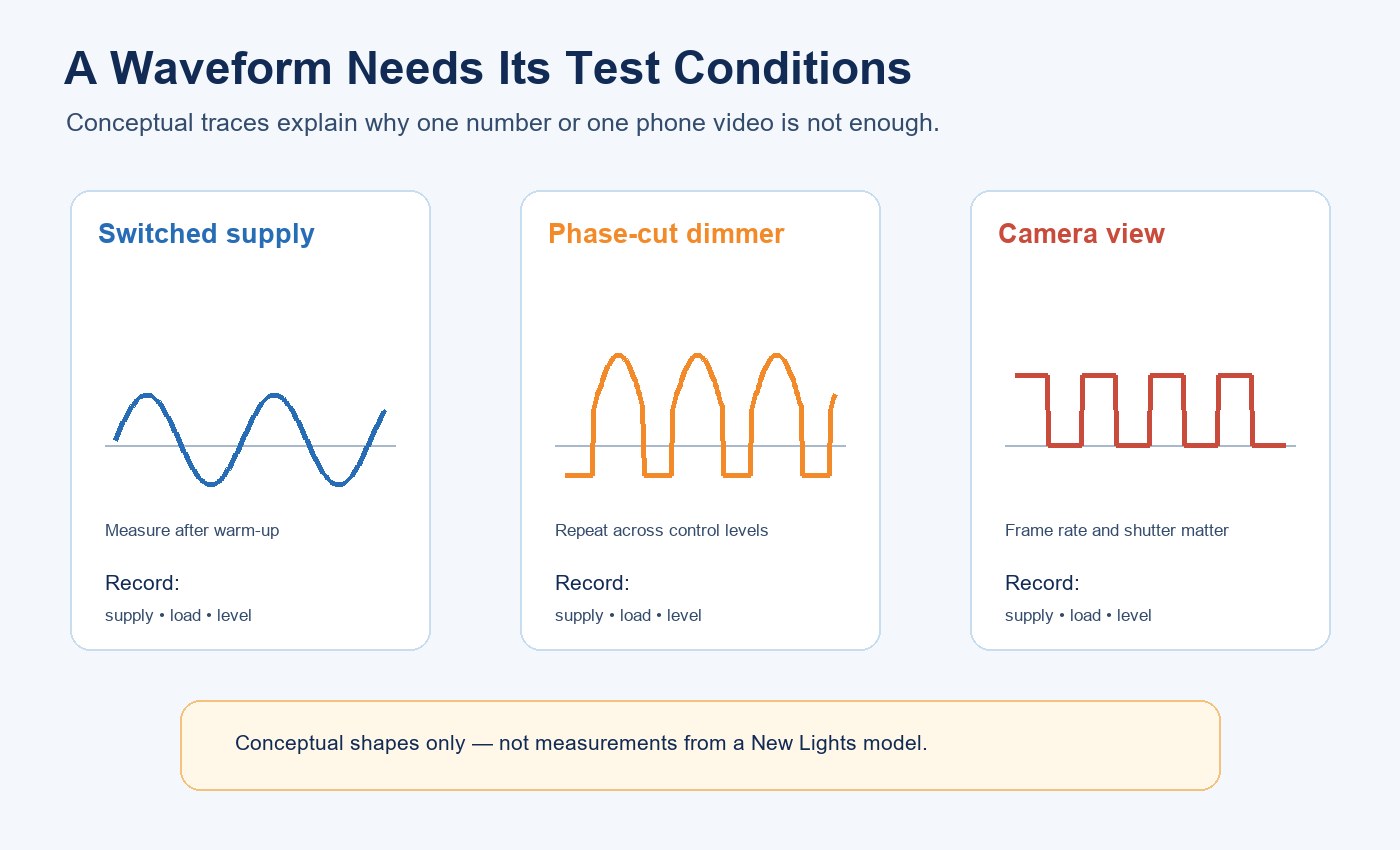
A defensible evaluation captures light output over time with an appropriate photodetector or flicker meter. The report should identify sample, supply, control, load, dimming level, warm-up period, detector, sampling method and analysis method. Without these conditions, a number cannot be reproduced or compared reliably.
Useful outputs can include fundamental frequency, waveform shape, percent modulation and application-relevant metrics such as PstLM and SVM. These metrics address different temporal effects. No single value describes every observer, moving object or camera, so acceptance criteria must follow the application and applicable procurement requirements.
The commercial lighting UGR, CRI and flicker guide places temporal behavior alongside other application metrics. It does not make those metrics interchangeable.
Build a Procurement Test Matrix
Define the test conditions before samples arrive. Include direct switched operation and each approved control. Add full output, intermediate points and minimum stable output; minimum and maximum circuit loads; cold start and warmed operation; and camera settings when video matters. If more than one mains region is offered, evaluate each rated condition relevant to the order.
| Approval item | Required record | Decision boundary |
|---|---|---|
| Product identity | Model, revision, base, lot and approved specification | Evidence applies only to the identified configuration |
| Electrical condition | Voltage, frequency, control and connected load | No transfer to untested circuits |
| Optical data | Raw waveform, frequency and agreed metrics | Compare only under matching methods |
| Dimming behavior | Stable range, start-up, transitions and warm state | Exclude unstable combinations or settings |
| Camera result | Camera, frame rate, shutter and exposure | Applies only to defined capture conditions |
| Change control | Driver, capacitor, filament and firmware revisions | Retest changes that can alter the waveform |
Use the LED lighting sample evaluation checklist to connect this test matrix with the wider product approval record.
Correct the Cause and Repeat the Same Test
The remedy must follow the isolated cause. It may involve repairing a poor connection, replacing a damaged holder, selecting a compatible switch or dimmer, bringing the connected load into the control’s supported range, or replacing a defective lamp. Driver or component changes belong to engineering after external causes have been excluded.
Repeat the original observation and measurement after one controlled change. If several components change together, the symptom may disappear without revealing which action solved it. Preserve the original and corrected records so the result can be transferred to incoming inspection and production change control.
Convert the Result into an RFQ Requirement
Ask the supplier for the current electrical rating, dimming status, approved controls, stable dimming range, load conditions and waveform test method. Provide the target mains condition, socket, number of lamps, controls and camera requirements. Request raw waveform or instrument exports where temporal performance is a purchase criterion.
If first-party sample evidence or a controlled production revision is needed, review the New Lights factory and manufacturing capabilities. To submit a lamp, dimmer and application matrix, contact New Lights with the exact operating conditions.
Frequently Asked Questions
Why does an LED filament bulb flicker on a dimmer?
The dimmer changes the incoming waveform, and the lamp driver may not remain stable at every control level or connected load. Test the exact lamp, dimmer and lamp count.
Does visible flicker always mean the bulb is defective?
No. The cause may be the lamp, a loose connection, the supply or an incompatible control. Isolate lamp and circuit variables before assigning the fault.
Can a smartphone prove that a bulb is flicker-free?
No. A phone is useful for screening, but shutter, frame rate, exposure and sensor readout affect the result. Acceptance needs defined optical measurement.
What should a flicker report include?
Identify the exact sample, supply, control, load, dimming level, warm-up, detector, sampling and analysis method, plus waveform data and the selected metrics.
Is a lamp that looks steady suitable for video?
Not necessarily. Test it with the intended cameras, frame rates, shutter settings and dimming conditions.
Editorial Sources
- New Lights, “Decorative Letter LED Filament Bulbs”: https://new-lights.com/products/decorative-ambient-lighting/decorative-led-bulbs/decorative-letter-led-filament-bulbs/
- U.S. Department of Energy, “Flicker Research”: https://www.energy.gov/cmei/ssl/flicker-research
- U.S. Department of Energy, “Flicker Measurement and Standards”: https://www.energy.gov/cmei/ssl/flicker-measurement-and-standards












