


Installing an LED panel downlight starts before anyone cuts the ceiling. The installer needs the exact luminaire, its cutout requirement, the available ceiling void, the driver or junction-box arrangement, and the rules that apply to the building. A slim round or square light may look simple from below, while the parts above the ceiling determine whether it will fit, remain serviceable and operate within its rated conditions.
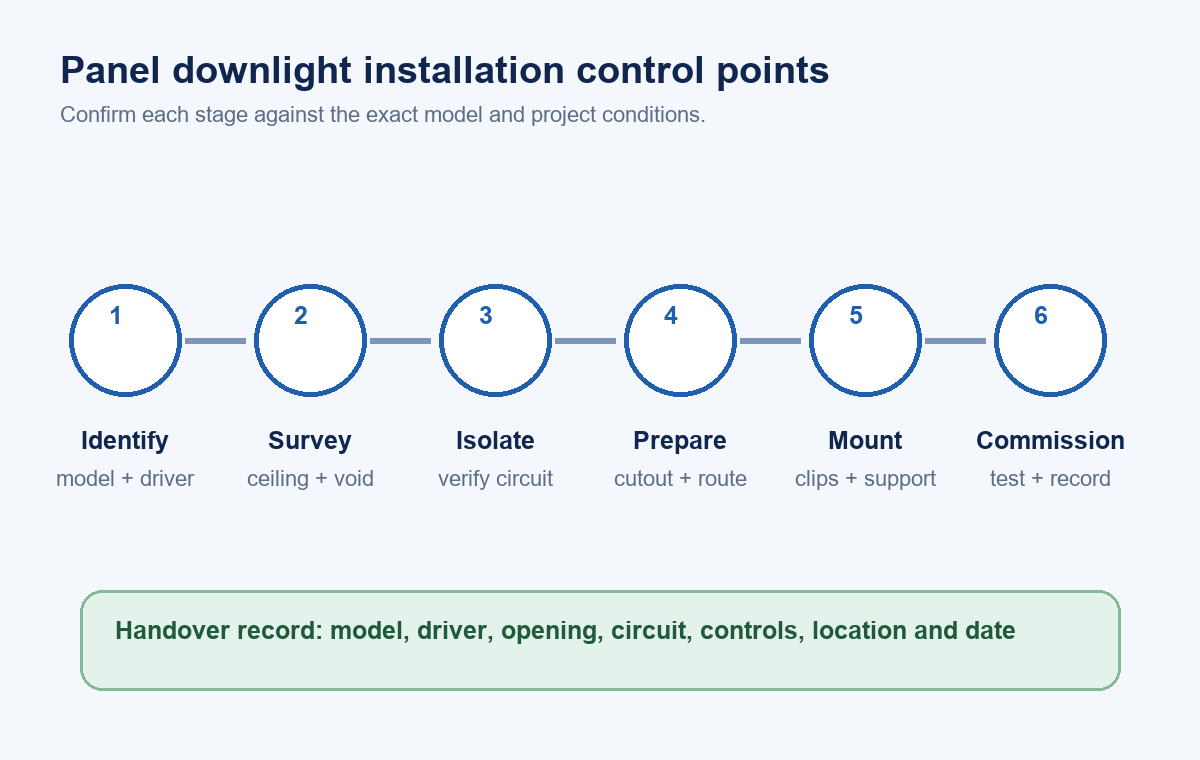
The practical sequence is to identify the product, survey the location, isolate and verify the circuit, prepare the opening, place the driver and cable correctly, engage the mounting system, and commission the finished installation. The exact product instructions and project documents control each step.
Identify the Exact Panel Downlight
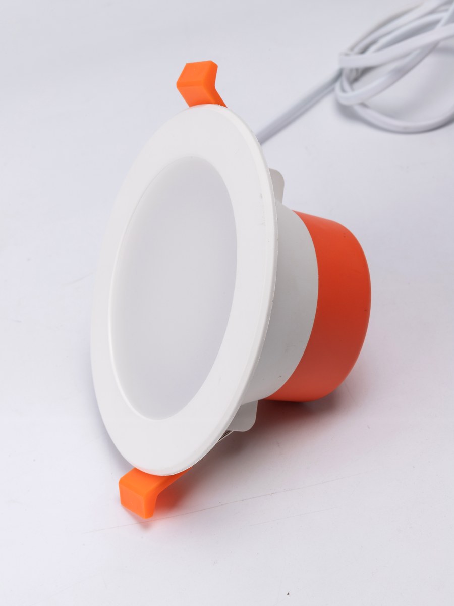
“Panel downlight” is used for several constructions. A product may have a separate driver, a rear-integrated driver, an integral junction box, fixed spring clips, adjustable clips, or an adapter intended for an existing housing. These differences affect the opening, void depth, cable route and service access.
Record the model code and compare the label with the datasheet and installation instructions. At minimum, confirm the rated input, driver arrangement, cutout, outside dimensions, ceiling-thickness range, required clearance, permitted orientation, environmental classification, control method and destination market. If the delivered product or driver does not match the approved submittal, resolve the mismatch before installation.
Buyers comparing formats can start with the LED panel light range. The recessed side-emission small panel light illustrates a spring-clip format, while the adjustable-cutout recessed small panel light shows why the mounting mechanism must be checked for the exact model. Product-page dimensions or ratings apply only to the models stated there.
| Item to verify | Why it changes the installation | Evidence to use |
|---|---|---|
| Cutout and tolerance | Determines whether the clips or mounting ring can grip | Exact model drawing or template |
| Ceiling thickness | Affects clip reach, trim seating and support | Product instructions plus site measurement |
| Driver or junction box | Controls placement, access, cable route and enclosure needs | Supplied assembly and wiring diagram |
| Insulation and clearance | Affects heat transfer and permitted contact | Product marking and project requirements |
| Dimming or controls | Changes driver compatibility and commissioning | Exact driver label and approved control schedule |
| Environment | Determines whether the model suits the location | Product certification and project classification |
Survey the Ceiling and Hidden Space
Check the proposed center point from above where access is available. Otherwise, use an appropriate detection and investigation method before cutting. Look for joists, channels, pipes, sprinkler lines, ducts, cables, insulation, vapor barriers and fire- or acoustic-rated ceiling components. A small visible trim does not mean the driver and cable will fit in the remaining void.
Measure the clear depth and usable side space, not just the ceiling face. Confirm that the driver can be positioned without resting on the luminaire unless the instructions allow it. Plan how the driver will be reached later. If the ceiling forms part of a tested fire, acoustic or air-control assembly, coordinate the opening and any protective enclosure with the approved project detail.
The opening also has to avoid weak or damaged board. For an existing hole, measure across several directions because older cutouts may be irregular. The LED panel light size guide explains how visible dimensions and planning dimensions serve different purposes.
Use the Exact Cutout
The trim diameter is not the cutout diameter. Mark the manufacturer-specified opening and verify the printed template against a measuring tool before using it. A copied template may have changed scale.
An undersized opening can damage the ceiling or force the housing. An oversized opening may leave too little material for the clips to engage. Trim overlap can hide a small visual gap, but it does not restore the strength of a damaged edge. When an existing opening is outside the permitted range, use an approved adapter or repair detail, or select a suitable model.
For projects involving larger luminaires or multiple mounting formats, use the separate guide to four LED panel-light mounting methods. That article covers lay-in, recessed, surface and suspended systems; the workflow here remains focused on slim recessed panel downlights.
Confirm Insulation, Clearance and Driver Placement
Thin construction does not establish insulation-contact suitability. Read the marking and instructions for the luminaire, driver and junction box. The permitted condition may distinguish loose-fill insulation, batt insulation, sprayed foam or required separation. A fire-rated claim likewise depends on the complete tested system, not the visible shape of the light.
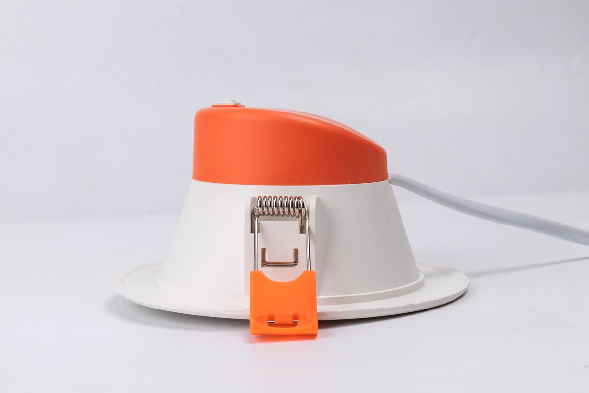
The driver or junction box must be supported and located as specified. Check whether it may rest above the ceiling, whether it must be fixed, what clearance it needs, and how future replacement access will be maintained. Do not extend a proprietary lead, substitute a driver or group boxes together unless the approved documentation permits that arrangement.
Isolate and Verify the Electrical Circuit
A wall switch is not an isolation device for planning purposes. The circuit may have another source, shared conductors or a switch that can be operated by someone else. The qualified person should identify the circuit, apply the site’s isolation controls, verify the test instrument, test for absence of voltage at the work point, and recheck the instrument in accordance with the adopted safe-work procedure.
In covered US workplace work, OSHA requirements address deenergization, controls against reenergization, tagging and verification. Other jurisdictions use their own legal and technical framework. Where the circuit cannot be shown to be deenergized under the applicable procedure, normal installation work should stop.
Prepare the Opening and Cable Route
Once the location and safe condition are established, mark the center and cutout. Recheck alignment with the lighting layout, nearby fittings and repeated grid lines. Protect occupants and equipment from debris, support fragile ceiling material, and use a cutting method suitable for the substrate.
Inspect the finished edge before inserting the luminaire. Confirm the final opening dimensions, ceiling condition and route for the supply cable or driver lead. Sharp edges, unsupported cable and tight bends should be corrected using the specified protection and strain relief.
Connect the Supplied System
The connection method comes from the exact instructions. Some products accept line voltage in a driver or junction box; others connect the luminaire to a separate driver through a supplied low-voltage connector. Dimmable versions may use phase-cut, 0–10 V, DALI or another interface.
The qualified installer should check conductor size and temperature rating, earthing or double-insulation requirements, polarity where applicable, terminal capacity, strain relief and enclosure closure. Do not infer conductor colors or terminal positions from a similar-looking product. Loose splices above the ceiling and unapproved driver substitutions create avoidable electrical, thermal and service risks.
Before closing the enclosure, inspect for exposed copper, trapped insulation, damaged connectors and unsupported cable. Covers and entries should be fully secured before the circuit is energized.
Fit the Spring-Clip Panel
For a typical spring-clip format, the driver and cable are guided into the void, the clips are compressed, and the luminaire is inserted until the clips engage the rear face of the ceiling. Hand position and insertion order vary by model, so follow the supplied instructions and protect fingers from the clip force.
After seating the light, check that the trim lies flat, both clips are engaged, and the cable is not pinched between the housing and ceiling. The panel should not bow the ceiling or depend on a weak edge. Ceiling tiles that cannot resist clip pressure may need a support frame or another approved method.
Commission the Installation
Before reenergization, account for tools and temporary protection, close enclosures, verify support and clearances, and ensure the work area is ready. Restore power under the site procedure and observe startup, switching, dimming and any connected controls.
Compare repeated units for stable output, color consistency, noise, cycling and trim alignment. Investigate flicker, buzzing, delayed start or glow when off as a system issue that may involve the driver, control, wiring or supply. Do not alter the approved wiring arrangement as a trial fix.
Record the installed model, driver, location, circuit, control, adapter and installation date. Retain the instructions, certificates and approved submittal with the project record. New Lights’ factory and manufacturing overview provides context on product and production coordination; project acceptance still follows the evidence for the exact delivered model.
| Commissioning check | Acceptable observation | If the result is not acceptable |
|---|---|---|
| Mechanical seating | Trim is even; clips or supports are fully engaged | Isolate, remove and inspect the opening and mounting parts |
| Cable and driver | No pinching; enclosure closed; location remains serviceable | Reposition under the product instructions |
| Startup | Stable operation without cycling or abnormal delay | Check supply, driver and control compatibility |
| Dimming or controls | Required range and commands operate consistently | Compare exact driver and approved control schedule |
| Batch appearance | Output and color are consistent with the approved sample | Quarantine affected units and review batch evidence |
| Documentation | Model, driver, circuit and location are traceable | Complete the record before handover |
Frequently Asked Questions
Can I install an LED panel downlight myself?
Fixed wiring may require a licensed or otherwise qualified electrician, permits and inspection. Apply the rules for the project location and follow the exact product instructions.
Is turning off the wall switch enough?
No. The circuit should be isolated against reenergization and verified deenergized with the applicable procedure and test equipment.
How do I choose the cutout size?
Use the cutout and tolerance for the exact model, then confirm the finished opening. Do not use the visible trim diameter as the hole size.
Can a slim panel downlight touch insulation?
Only when the exact luminaire, driver and installation condition are permitted for that type of contact. Thin construction alone does not establish the rating.
Where should the driver or junction box be placed?
Place and support it as the instructions require, with the specified clearance, environmental suitability, cable protection and service access.
Prepare a Traceable Installation Review
The useful installation record connects the exact product to the actual ceiling and circuit. Share the model, cutout, ceiling type and thickness, void depth, insulation condition, voltage, controls, destination market and project quantity when requesting support. Contact New Lights with those project details so the discussion can start from the correct product and site conditions.
Editorial Sources
- IEC, IEC 60598-2-2:2023 — Particular requirements for recessed luminaires: https://webstore.iec.ch/en/publication/68002
- US Occupational Safety and Health Administration, 1926.417 Lockout and Tagging of Circuits: https://www.osha.gov/laws-regs/regulations/standardnumber/1926/1926.417
- US Occupational Safety and Health Administration, STD 01-16-007 — Electrical Safety-Related Work Practices: https://www.osha.gov/enforcement/directives/std-01-16-007
- UL Solutions, Recessed Luminaires Intended for Contact with Expandable Foam: https://www.ul.com/sites/default/files/2024-10/AHL23CS1146123_Recessed_Foam_Luminaires_Infosheet_Final_Digital.pdf












