


LED panel size is often written as a simple label—2×2, 2×4 or 600×600—but that label is not enough to prove that a panel will fit. A project needs to distinguish the nominal size family from the luminaire’s actual outside dimensions, the ceiling opening or grid module, and any recessed or surface-mount accessory.
The correct selection also depends on output, distribution, controls and layout. A larger panel is not automatically brighter, and two panels with similar front dimensions may require different driver space or mounting hardware.
Common Size Families
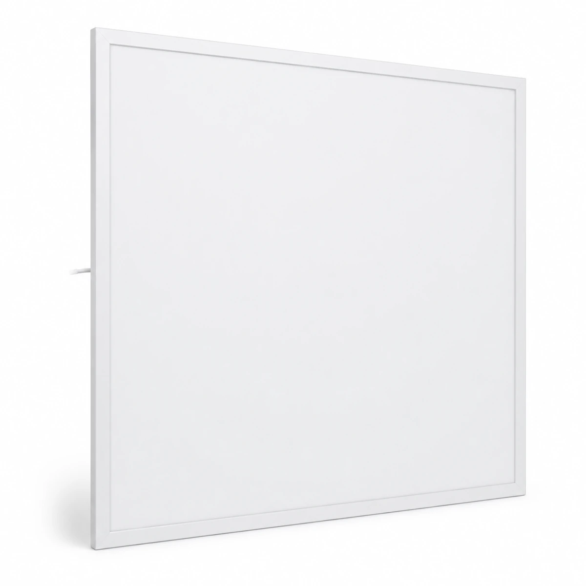
US commercial suspended ceilings commonly use the 1×4 ft, 2×2 ft and 2×4 ft troffer families identified in Department of Energy retrofit guidance. Metric markets commonly describe panels with families such as 600×600 mm or 1200×300 mm. Compact square, rectangular and round panels are also available for other ceiling systems.
| Nominal family | What the name usually communicates | What still needs verification |
|---|---|---|
| 1×4 ft | Long, narrow US grid/troffer family | Actual length and width, grid fit, depth and output |
| 2×2 ft | Square US grid/troffer family | Actual body dimensions, support and accessory compatibility |
| 2×4 ft | Large rectangular US grid/troffer family | Actual dimensions, handling, support, output and layout |
| 600×600 mm | Square metric panel family | Actual size relative to the specific grid and regional standard |
| 1200×300 mm | Long, narrow metric family | Actual dimensions, grid or frame and driver location |
| Other compact formats | Recessed or surface decorative/functional panels | Cutout, trim size, clip/frame and ceiling depth |
These names are useful for organizing a product search. They are not installation drawings.
Four Different Dimensions Can Matter
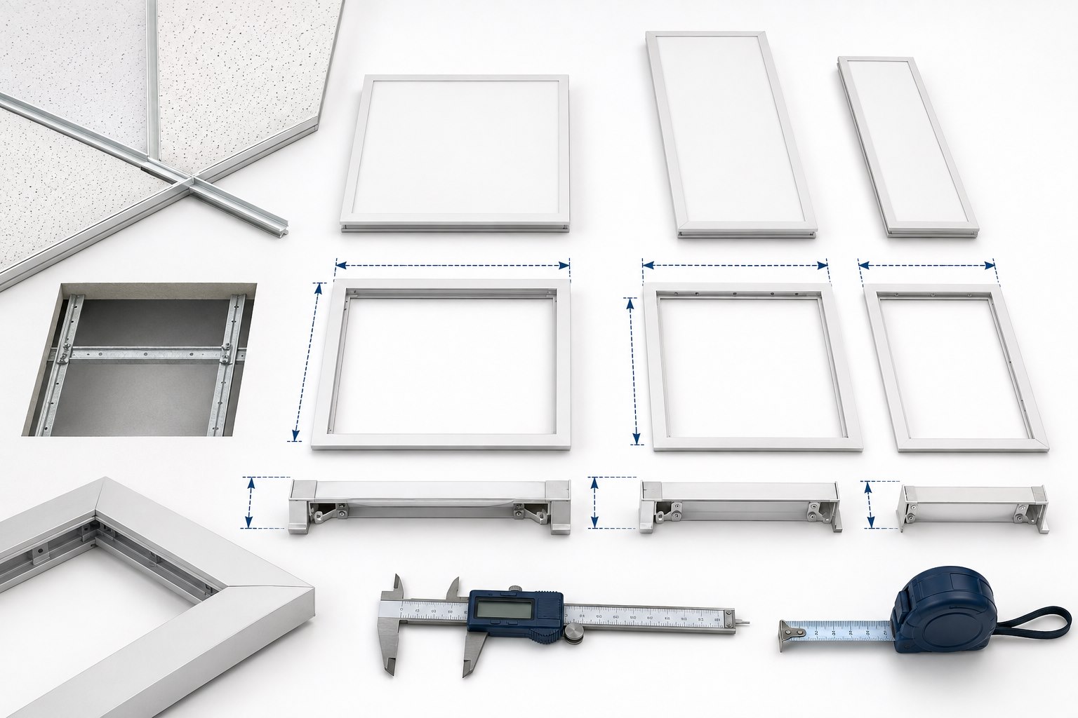
1. Nominal Size
The nominal size identifies a market family or ceiling module. It simplifies communication but may round the actual dimensions.
2. Actual Luminaire Dimensions
The product drawing should list the real length, width and depth of the panel. Lay-in products are commonly made slightly smaller than the nominal grid module, but the exact allowance varies. Compare the drawing with the measured site, not with a rough conversion.
3. Cutout Size
A recessed product may require an opening that is different from both the nominal size and visible trim. The approved recessed frame or clip system controls this value. Never cut a ceiling from the front-face dimensions alone.
4. Mounting-Accessory Dimensions
A surface frame adds depth and may change the outside footprint, cable entry and fixing pattern. A suspension kit adds ceiling points and cable ranges. These accessory dimensions can determine fit even when the panel itself matches the desired footprint.
How to Read a Panel Drawing
Begin with the drawing revision and exact model code. A product family may include several lengths, widths, depths, power options or mounting versions, so the family name alone is not enough to select a row.
Locate each dimension by its role:
- Outside length and width: the physical body that must pass through, sit within or cover the ceiling condition.
- Visible trim or luminous area: the portion seen from the room; this may differ from the body size.
- Overall depth: the panel body plus any fixed rear enclosure.
- Cutout: the opening required by a recessed mounting system.
- Driver or junction-box envelope: the additional space required above or beside the panel.
- Fixing or suspension points: the coordinates used by frames, clips, cables or safety restraints.
Check whether dimensions include connectors, cable bends, brackets or removable covers. A drawing may show the body accurately while the installation still needs extra space to connect and service the driver. Where the ceiling void is tight, coordinate the complete assembly rather than comparing only the front face.
Record dimensions in one unit system for the project and retain the original values from the supplier drawing. Repeated conversion and rounding can turn a small clearance into a site conflict.
Imperial and Metric Labels Are Not Interchangeable Proof
Two feet is close to 610 mm, but that does not make a 2×2 panel identical to a 600×600 panel. Ceiling grids, product tolerances and actual body dimensions differ across markets and models.
For replacement work, record the existing opening or grid cell in millimeters, even if the project normally uses feet and inches. Then compare those measurements with the exact proposed product drawing. Do not approve a substitute because its nominal label appears equivalent.
Size Selection Starts With the Ceiling
Suspended Grid Ceiling
Measure the clear grid opening, module direction and available void. Identify whether the existing luminaire uses additional supports or restraints. Confirm that the new panel is intended for that grid and that the driver and connections can be supported and accessed. The LED panel installation guide compares lay-in, recessed, surface and suspended methods.
Hard Ceiling With Recessed Opening
Obtain the exact cutout drawing and mounting-kit instructions before marking the ceiling. Check void depth, obstructions, insulation or fire requirements, driver access and the ability of the approved frame or clips to engage the ceiling construction.
Surface Mount
The surface frame, not only the panel, determines the installed size. Check frame assembly, outside dimensions, cable entry, anchor pattern and driver space. Verify that the ceiling structure and fixing method support the complete assembly.
Suspended Installation
Confirm panel attachment points, ceiling anchor locations, suspension range and power-feed routing. Large rectangular panels require coordinated leveling and support; do not infer cable spacing from the panel corners alone.
Do Not Select Light Output From Footprint Alone
Two panels with the same footprint can have different lumens, watts, efficacy, distribution, glare characteristics and control options. The quantity and spacing needed in a room depend on the lighting task, mounting height, reflectances, obstructions and target illuminance.
Compare at least:
- Initial and maintained lumens.
- Complete-luminaire watts.
- Photometric distribution.
- Spacing and uniformity in the proposed layout.
- Glare criteria relevant to the project.
- Color temperature and color-rendering requirements.
- Dimming, sensor, emergency and control options.
A 2×4 panel is not automatically the correct replacement for a 2×4 fluorescent troffer. A retrofit kit or a different layout may better suit the existing housing and lighting objective. DOE guidance treats lamp replacement, retrofit kits and complete luminaire replacement as distinct upgrade paths.
Coordinate the Panel With the Lighting Layout
Panel size affects the visual rhythm of a ceiling, but the lighting calculation should decide quantity and spacing. Use the selected model’s photometric file and complete-luminaire data to review illuminance, uniformity and glare at the intended mounting height. Account for ceiling height, task position, wall and ceiling reflectance, partitions and the maintenance condition of the space.
Controls can also change the required product configuration. A daylight-controlled perimeter zone, occupancy-controlled meeting room and continuously operated corridor may use similar panel footprints but different drivers, sensors or emergency arrangements. Confirm those options before the ceiling schedule and order are released.
For a retrofit, compare the proposed layout with the existing circuit and control zones. Reusing fixture positions may reduce work, but it should not automatically override the target distribution or control strategy.
A Practical Selection Workflow
- Measure the site. Record the grid cell or opening, ceiling construction, depth and access.
- Identify the mounting method. Lay-in, recessed, surface and suspended systems use different fit criteria.
- Define the lighting target. Record illuminance, distribution, glare, CCT, CRI and controls.
- Shortlist actual models. Use model drawings and photometric files, not nominal size alone.
- Match accessories. Confirm frames, clips, cables, drivers and emergency/control components.
- Coordinate electrical details. Check voltage, driver placement, dimming and service access.
- Review a sample. Verify physical fit, appearance and operation before production quantity.
Retrofit Measurement Checklist
For each location, record:
- Existing luminaire make, model and nominal size.
- Measured grid opening or ceiling cutout.
- Visible trim or frame dimensions.
- Ceiling type and void depth.
- Driver or junction-box space.
- Existing support and restraint method.
- Circuit voltage and control system.
- Emergency-lighting requirements.
- Target panel dimensions and approved accessory.
- Any conflicts with ducts, pipes, structure or insulation.
A useful site record combines overall ceiling photographs with close views of a scale, the opening and the fixture label.
Approve a Physical Sample
Before ordering a large quantity, place a representative panel and its actual mounting accessory in the intended ceiling condition. Check insertion clearance, visible gaps, frame coverage, driver location, cable entry, access and any required support or restraint. A tabletop sample can confirm appearance but cannot evaluate the ceiling interface.
Energize and commission the sample under the project procedure. Review start-up, dimming or control response, visual comfort, color appearance and the calculated lighting result. Record the approved model and accessory together; changing either one can change fit.
If the project has several ceiling types, openings or grid manufacturers, sample the variants that create different interfaces. Separate exceptions in the order schedule so installers do not resolve incompatible openings by cutting, bending or substituting hardware on site.
Frequently Asked Questions
Is a 600×600 panel exactly 600 mm square?
Not necessarily. It is often a nominal family description. Use the exact model drawing for actual dimensions.
Is a 2×2 panel the same as a 600×600 panel?
Do not assume they are interchangeable. Measure the ceiling system and compare the actual proposed product dimensions.
Does the panel size equal the recessed cutout?
Usually not as a general rule. The cutout comes from the selected recessed panel or mounting-frame drawing.
Which size produces more light?
Footprint alone does not determine output. Compare model lumens, watts, distribution and the proposed layout.
Can a lay-in panel be surface mounted?
Only when the manufacturer provides or approves a compatible surface-mount system for that panel.
Should a fluorescent troffer be replaced by the same nominal panel size?
It can be a starting point, but verify actual fit, support, photometrics, controls and whether a retrofit kit or complete luminaire is the better route.
Send Measurements With the Inquiry
Review the LED panel product families, use the LED panel installation guide to identify the mounting route, and send the grid or opening measurements, mounting method, target output, controls and destination market through the New Lights contact page. Final fit should be confirmed against the quoted model drawing and accessory list before ceilings or mounting frames are ordered.












