


An LED panel light is a broad-area luminaire designed to present a relatively large luminous surface from a flat or shallow housing.
It is not simply a sheet that emits light. A complete panel typically combines LED sources, optical components, a driver, structural and thermal parts, electrical connections and a mounting system. The exact stack differs among edge-lit, direct-lit and other product designs.
Understanding those parts helps buyers ask better questions about distribution, glare, color, flicker, controls, installation and maintenance. The New Lights LED panel light category provides examples of the product family, while this guide explains the system behind the luminous surface.
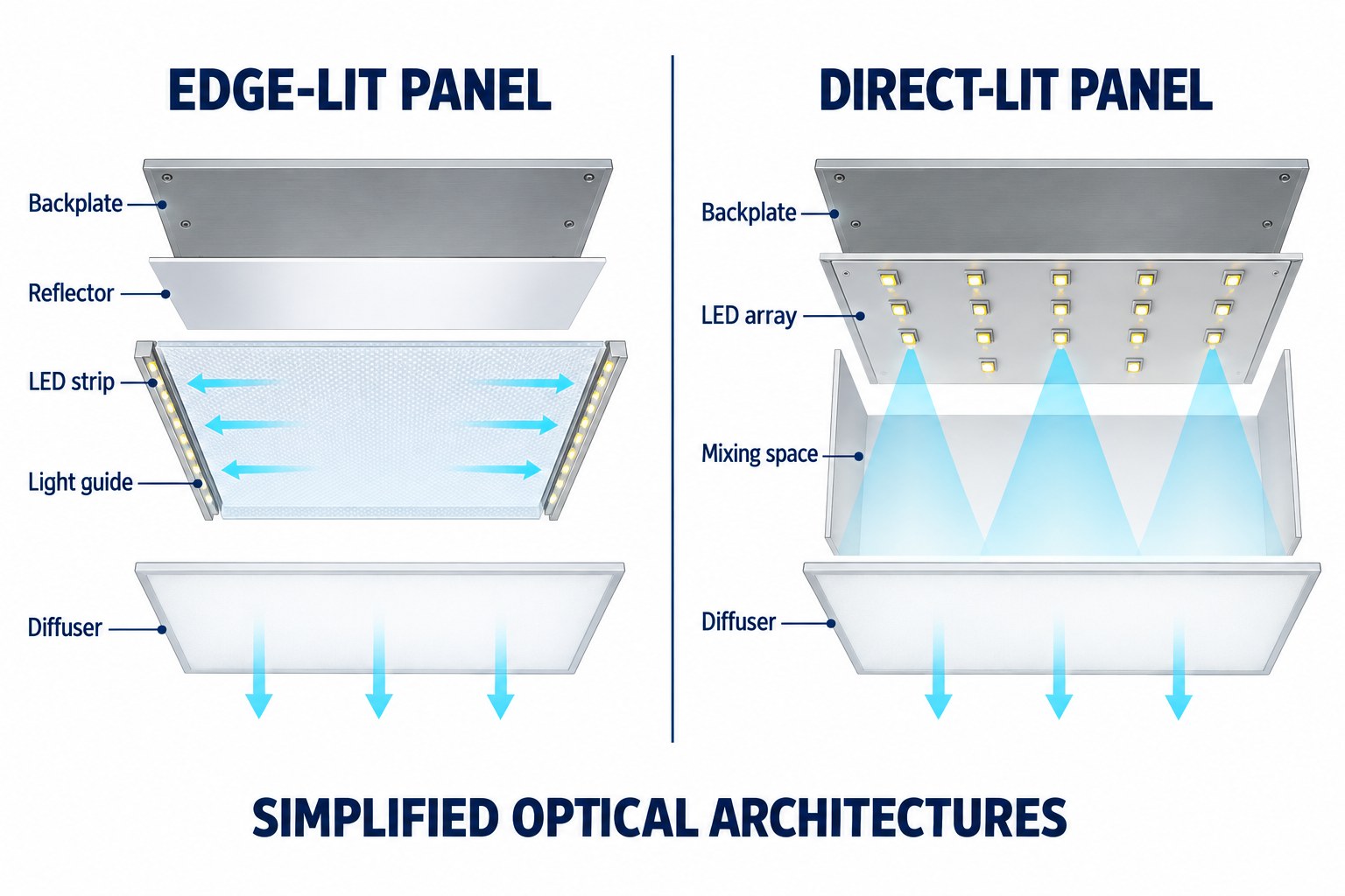
A panel is a luminaire, not only an LED source
DOE distinguishes a lamp from a luminaire: the luminaire is the complete fixture that holds and operates the light source and includes supporting components.
For an LED panel, the system boundary may include:
- LED packages mounted on boards or strips;
- a light guide or mixing chamber;
- reflectors, diffusers, films or lenses;
- a frame, backplate or housing;
- an LED driver;
- wiring and connectors;
- mounting brackets, surface frames or suspension hardware;
- optional controls, sensors or emergency components.
Not every panel contains every item in the same form. An exploded drawing must come from the exact model before it is used for specification, servicing or marketing.
How an edge-lit LED panel works
In an edge-lit architecture, LEDs are positioned along one or more edges of a light guide. Light enters the guide and is redirected across the luminous area by the guide structure, extraction pattern, reflector and diffuser system.
DOE R&D material identifies edge-illuminated waveguides as one flat-panel approach for creating a diffuse source. A simplified optical path is:
- LED packages generate light at the panel edge.
- The light enters the waveguide.
- Optical features extract and redistribute light across the surface.
- Reflective and diffusing layers manage losses, appearance and distribution.
- Light exits through the luminous face.
Uniformity depends on the LED spacing, coupling, guide material, extraction pattern, reflector, diffuser and mechanical assembly. “Edge-lit” describes the source location; uniformity, efficacy and edge brightness still require exact-model data.
How a direct-lit LED panel works
In a direct-lit architecture, LED packages or modules are arranged behind the luminous face. A mixing distance and optical system spread the light before it exits through the diffuser.
A simplified path is:
- LED packages emit toward the output area.
- The housing and optical cavity mix and redirect the light.
- A diffuser or lens system reduces images of individual sources and shapes distribution.
- The driver regulates electrical power to the LED array.
The distance between the LED array and diffuser, package spacing, optical design and housing reflectance influence thickness and uniformity. Direct-lit does not automatically mean thicker, more efficient or easier to service; compare the exact products.
Edge-lit and direct-lit are architecture labels
| Question | Edge-lit design | Direct-lit design |
|---|---|---|
| Source location | Along one or more edges of a waveguide | Behind the luminous face |
| Main optical element | Light guide plus extraction and diffusion system | Mixing cavity, lens or diffuser system |
| Uniformity risks | Edge brightness, guide pattern, corner or center variation | Visible source pattern, spacing variation or insufficient mixing |
| Thermal path | Heat from edge-mounted LED strips must reach the frame or other thermal structure | Heat from distributed LED boards must transfer to the backplate or housing |
| Evidence required | Cross-section, uniformity, photometry, thermal and material data | LED layout, optical spacing, photometry, thermal and material data |
Neither column is a universal advantage list. Product engineering, materials and operating conditions determine the result. If the project is deciding between panel and point-source ceiling lighting, the panel-versus-downlight planning guide addresses that separate room-layout decision.
The LED source and board
LED packages convert electrical energy into light and heat. They may be mounted on linear strips, rigid boards or other carriers, depending on architecture.
The source selection influences output, color, efficacy, thermal loading and package density, but complete-panel performance also depends on the driver, optics and temperature. A supplier should identify the exact model’s output and color data rather than relying on a general LED brand statement.
For long production runs, component change control matters. A substitute LED package can alter color, distribution, forward voltage and thermal behavior even when the panel looks unchanged from the outside.
Optical layers and the luminous surface
The optical system transforms small, intense LED sources into a larger luminous area. Depending on design, it may include:
- a light guide plate;
- a reflector or reflective film;
- diffusion films;
- a prismatic or opal diffuser;
- lenses over individual LEDs;
- a mixing chamber or reflective housing.
DOE CALiPER studies of troffer and retrofit products show how LED boards, drivers and optical components can be combined in different ways. They also show that distributions vary; some products may create a broad cosine-like pattern while others shape light differently.
The diffuser’s appearance does not reveal the complete photometry. Request the intensity distribution or IES file for layout work.
The driver and electrical system
The LED driver converts and regulates electrical power for the source. Its design affects:
- input voltage and frequency range;
- power factor and harmonic behavior;
- output current and LED loading;
- dimming protocol and minimum level;
- flicker behavior;
- protection and fault response;
- lifetime and thermal conditions;
- compatibility with sensors, controls and emergency systems.
“Dimmable” is incomplete without the protocol, control compatibility and performance range. Likewise, “flicker-free” requires a measurement method, metric and operating conditions.
DOE’s flicker characterization included LED troffer products with very different results, including under dimming. That evidence supports a product-level check, not a claim that panel lights as a category have one flicker behavior.
Frame, housing and thermal path
The frame or housing establishes dimensions, supports optical layers and mounting, protects components and can participate in heat transfer. A backplate may support LED boards and help spread heat in direct-lit products; edge-lit products may conduct heat from LED strips toward the perimeter structure.
Material names alone do not establish thermal performance. Evaluate the complete thermal design, permitted ambient conditions and any test evidence for the exact configuration.
Mechanical quality also affects optical consistency. Gaps, layer movement, frame distortion or contamination can change the visible surface even if the LEDs continue operating.
Common mounting approaches
Panel luminaires may be designed for:
- recessed installation in a compatible modular ceiling;
- surface installation with a dedicated frame or bracket;
- suspension with an approved cable system;
- recessed installation in a purpose-made opening.
The product instructions determine which methods are permitted. Verify actual dimensions, weight, support points, driver location, clearance, wiring access and ceiling requirements. See the LED panel mounting-method guide and LED panel size-planning guide for the installation and ceiling-fit questions that follow the definition stage.
Panel and troffer are related but not always interchangeable terms. A troffer is commonly a rectangular luminaire designed for a modular ceiling grid. Some flat panels serve that application, while other panels are surface mounted, suspended or shaped differently. A retrofit kit may create a panel-like luminous face while retaining an existing troffer housing.
Which performance terms matter?
When comparing models, request evidence for:
- total luminaire lumens;
- complete-luminaire input power and efficacy;
- intensity distribution and photometric file;
- luminous-surface uniformity;
- glare or luminance data with conditions;
- CCT, color rendering and color consistency;
- flicker metrics at full and dimmed output;
- driver and control compatibility;
- lumen maintenance and driver-life basis;
- dimensions, mounting and service method;
- environmental and certification scope.
No single metric proves a good panel. High efficacy with unsuitable distribution may not meet the room task. A low-glare claim without room or luminance conditions may not predict visual comfort. Use a supplier evidence map to keep component descriptions and performance claims connected:
| Question | Evidence to request | Decision supported |
|---|---|---|
| What is the optical architecture? | Cross-section or component drawing for the exact model | Confirms edge-lit, direct-lit or another construction |
| How does it distribute light? | Complete-luminaire photometric file and report | Supports spacing, uniformity and glare review |
| How is the source operated? | Driver model, input/output data and control protocol | Supports supply, dimmer, sensor and emergency compatibility |
| How consistent is the luminous face? | Uniformity method, sample inspection and agreed acceptance criteria | Separates visible appearance from a generic diffuser description |
| How does it behave over time? | Lumen-maintenance basis, driver-life basis and thermal conditions | Connects lifetime planning with the complete luminaire |
| Which market documents apply? | Certification or test documents with model and configuration scope | Prevents evidence from another variant being substituted |
For electrical waveform and driver evidence, the flicker, power factor and THD buyer checklist provides a focused review path.
Where are LED panels used?
Panel lights are commonly considered for broad ambient lighting in offices, classrooms, meeting rooms, corridors, healthcare or public interiors, retail support areas and selected residential spaces.
Application suitability is conditional. A classroom may need careful whiteboard and flicker review. An office may prioritize screens, uniformity and controls. Retail may need stronger vertical and merchandise lighting than a panel-only system provides.
The definition article explains the technology; actual selection requires the room, ceiling and photometric brief. The commercial LED panel selection guide turns those inputs into a project workflow.
How should buyers verify a panel?
- Confirm whether the product is edge-lit, direct-lit or another architecture.
- Obtain the exact model drawing and component description.
- Check complete-luminaire photometric and electrical data.
- Verify driver, dimmer, sensor and emergency compatibility.
- Confirm mounting accessories and ceiling conditions.
- Review model-level certification and market scope.
- Inspect a sample for luminous-surface appearance, color and construction.
- Use calculations or a mock-up for the intended room.
- Record the approved LED, driver, optical and mechanical configuration.
To request model-level information, contact New Lights with the application, ceiling type, room dimensions, controls and destination market.
Frequently asked questions
Is an LED panel the same as a troffer?
Not always. A troffer is commonly defined by its rectangular ceiling-grid application. Some LED panels function as troffers, while other panels are surface mounted, suspended or used in different ceiling systems.
Are all LED panels edge-lit?
No. Edge-lit and direct-lit are two common architectures, and other variations exist. Verify the exact product.
Which is better, edge-lit or direct-lit?
Neither is universally better. Compare dimensions, uniformity, distribution, thermal design, efficiency, service and project fit using model data.
Do LED panels always have low glare?
No. Glare depends on luminous-area brightness, optics, room geometry, layout and viewing direction. Check applicable data and the proposed room.
Are all panel lights flicker-free?
No. Driver and control design influence flicker, especially under dimming. Request measured model-level evidence.
Can one panel be recessed, surface mounted and suspended?
Only when the manufacturer provides approved methods and accessories for that model. Do not improvise a mounting conversion.
Can the driver be replaced?
It depends on the product design and service instructions. Check access, approved replacement part, electrical matching and certification implications.
Does a thinner panel perform better?
Thinness is a mechanical characteristic, not proof of optical, thermal or electrical quality. Evaluate the complete luminaire.
Editorial sources
- U.S. Department of Energy, “Luminaires”: https://www.energy.gov/cmei/buildings/luminaires
- U.S. Department of Energy, “Lighting R&D Program: Luminaire Integration”: https://www.energy.gov/sites/default/files/2021-06/ssl-lighting-rdmtg-luminaireintegration-mkt-expcts-feb2021.pdf
- U.S. Department of Energy, “CALiPER Exploratory Study: Recessed Troffer Lighting”: https://www1.eere.energy.gov/buildings/publications/pdfs/ssl/caliper_recessed-troffer_2013.pdf
- U.S. Department of Energy, “Flicker Research”: https://www.energy.gov/cmei/ssl/flicker-research
- U.S. Department of Energy, “LED Basics”: https://www.energy.gov/cmei/ssl/led-basics












