


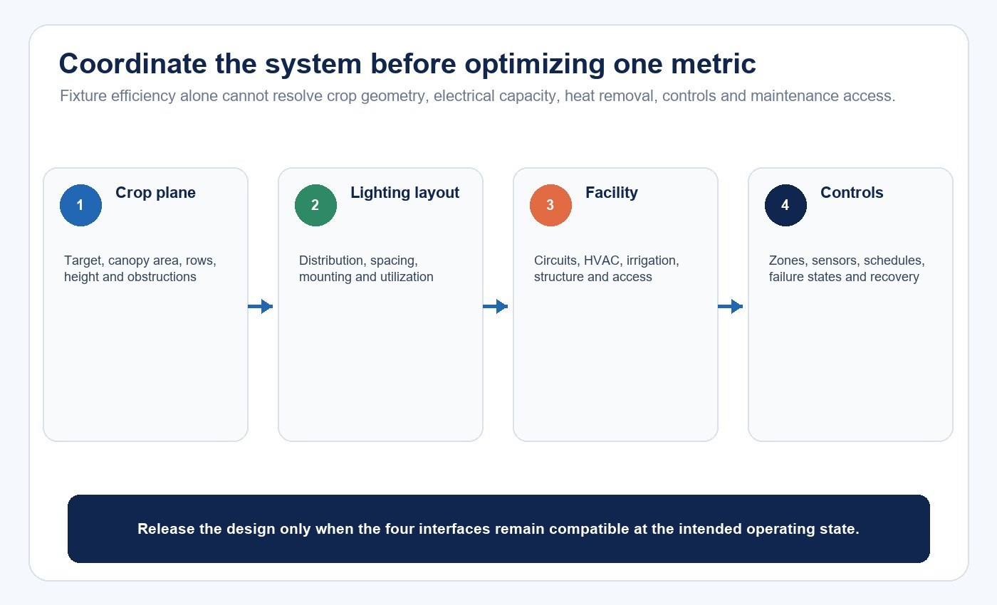
A horticultural lighting system is not defined by fixture wattage, spectrum labels or a layout drawing alone. It is the controlled delivery of light to a specified crop plane, coordinated with daylight, climate, irrigation, electrical infrastructure, controls, maintenance and production operations.
The project should begin with the crop and facility, not a product shortlist. Establish a measured baseline, define the biological and operational target, translate it into lighting and control requirements, compare model-bound equipment evidence, test a representative zone and commission the installed system. This sequence does not create a universal crop recipe; it creates an auditable way to validate a project-specific one.
Define the Crop and Production Brief
Record the crop, cultivar, propagation method, growth stage, plant density, canopy architecture, cycle length and production objective. Identify the person or team that owns the agronomic target and the evidence behind it, such as crop-specific research, historical production data or a controlled facility trial.
Clarify what the electric light is expected to accomplish. Possible jobs include supplementing seasonal daylight, maintaining a photoperiod, replacing daylight in an enclosed room, improving spatial consistency, influencing morphology or supporting a production schedule. These jobs can require different combinations of intensity, duration, spectrum, distribution and control.
Avoid broad labels such as “vegetative recipe” or “flowering spectrum” unless they are tied to a defined crop, stage, environment and evidence source. The grow-light fundamentals guide explains the basic quantities; this system guide begins where those quantities must become project inputs.
Establish a Measured Facility Baseline
The baseline lets the team separate lighting effects from other changes. Measure the current condition before replacing equipment or changing recipes.
| Baseline area | What to record | Why it affects the decision |
|---|---|---|
| Crop plane | Canopy dimensions, height, density, PPFD grid and daily light integral by zone | Defines where photons must arrive and exposes weak edges or layers |
| Daylight | Transmission, screens, structural shade, season and hourly variation | Determines the supplemental-light gap in a greenhouse |
| Climate | Air and leaf temperature, humidity, airflow and carbon-dioxide strategy | Light changes heat load and plant demand within the environment |
| Infrastructure | Supply, circuits, controls, mounting, irrigation, HVAC and service access | Limits feasible fixture, zoning and operating choices |
| Production | Crop timing, grade, morphology, losses, labor and maintenance | Creates the outcome baseline for a pilot comparison |
| Operations | Schedules, cleaning, alarms, failures and data availability | Determines whether the design can be repeated and maintained |
Use timestamps and zone identifiers so crop, environment, lighting and energy data can be compared over the same period. A change in crop response cannot be attributed confidently to lighting if cultivar, irrigation, density, season or climate changed at the same time.
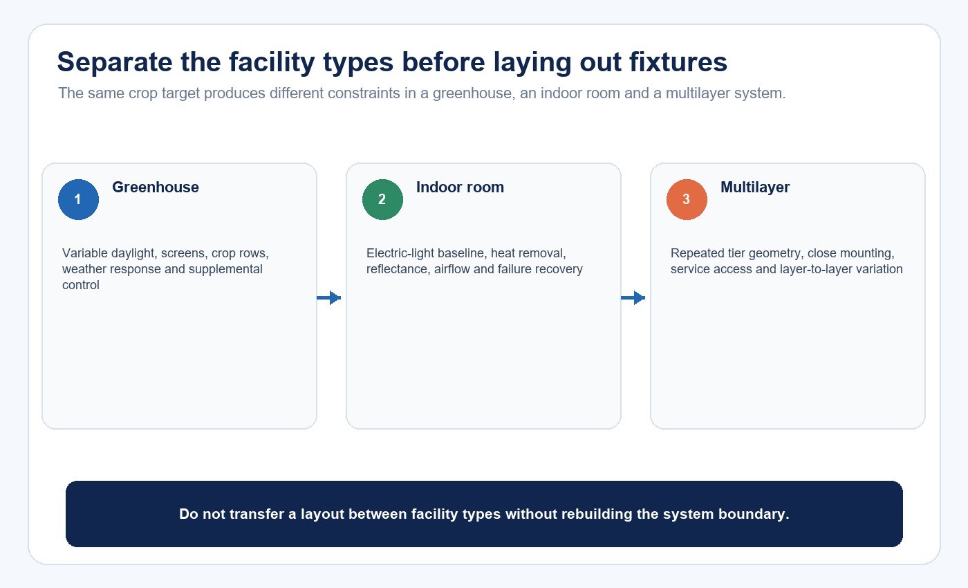
Separate Greenhouse, Indoor-Room and Multilayer Designs
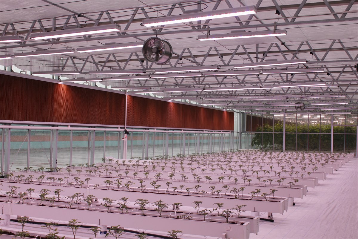
A greenhouse combines variable sunlight with electric supplementation. The design needs transmitted daylight at canopy level, a chosen design condition and a control strategy for changing weather, season and screen position.
A fully indoor room relies on electric lighting for the planned light environment. Electrical demand, heat removal, room reflectance, airflow, access, failure recovery and control reliability become central. A multilayer farm repeats these constraints on every tier, where small differences in mounting, reflectance, irrigation or airflow can create layer-to-layer variation.
Do not transfer a greenhouse layout directly to a rack system. The source-to-canopy distance, obstructions, surface reflections, service access and thermal behavior are different even when the crop target sounds similar.
Translate Crop Targets Into Lighting Requirements
Light quantity includes instantaneous PPFD and accumulated DLI. Timing includes photoperiod, start and end times, dark periods, daylight response, ramping and any dynamic schedule. Spectrum describes the photon distribution across relevant wavelengths and may change with control state. Distribution describes where those photons land across and within the canopy.
The USDA Natural Resources Conservation Service recommends determining the desired intensity, spectrum, DLI and pattern uniformity from current crop research and including sunlight when calculating DLI. That guidance is useful as a planning boundary: the target must belong to the crop and facility, not to a generic fixture advertisement.
If the project still needs an initial fixture quantity, use the separate grow-light coverage and PPFD method. That page owns photon-budget arithmetic and spacing validation. This article uses its layout output as one input to the wider system decision.
Treat Spectrum and Timing as Conditional Choices
A spectral label does not establish crop suitability. Compare the spectral quantum distribution at the actual operating state, then connect it to crop-stage evidence and the production objective. If channels are tunable, document the channel settings, range, transition behavior and resulting PPF, spectrum and input power.
The full-spectrum versus red-blue grow-light comparison explains why color appearance is not a substitute for spectral data. A project may also need to consider worker visibility, scouting, cameras or other operational needs, but these should remain separate from claims about plant response.
Holding DLI constant does not guarantee an identical result when intensity and timing change. Define the permitted combinations of PPFD, duration and schedule rather than approving only one daily total. Preserve the required dark period and coordinate the lighting window with irrigation, climate and labor.
Request Evidence for the Exact Fixture and Operating State
For every candidate, request data tied to the ordered model, revision and control state. The current DesignLights Consortium Horticultural Technical Requirements V4.0 is effective for applications from April 18, 2025 and defines qualification and reporting requirements for eligible LED horticultural fixtures or modules. V4.0 also removed lamps from its qualification categories, so an old claim or listing route should not be generalized to every product form.
Use the DLC framework as one evidence input, not proof that a fixture fits a crop or facility. Build a comparison file containing:
- tested PPF, input power and PPE;
- spectral quantum distribution for each relevant state;
- photon intensity or distribution data and model-specific PPFD maps;
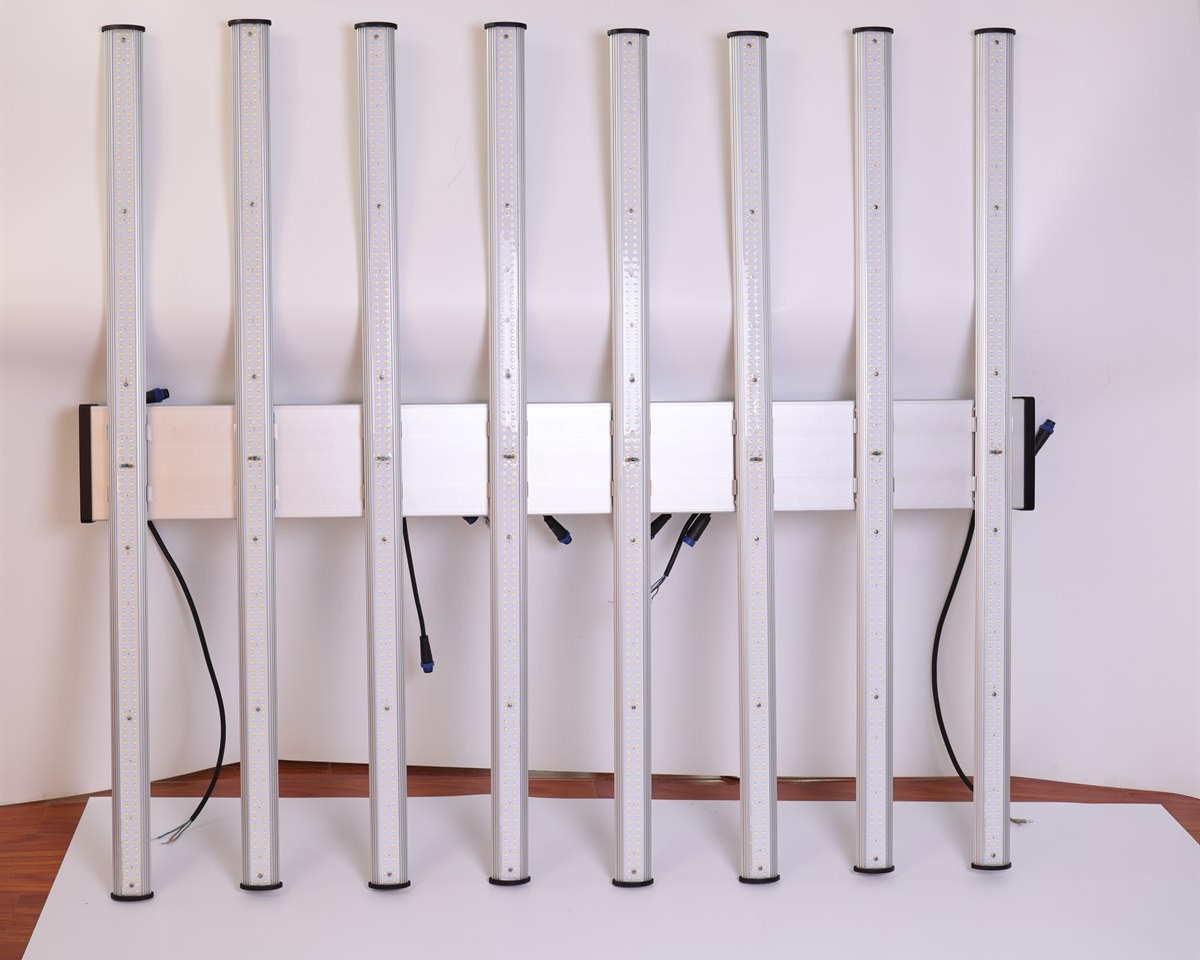
- dimensions, mass, mounting, connectors and service clearances;
- dimming range, channel behavior, protocol and fail states;
- power factor, harmonics, inrush and standby behavior where relevant;
- thermal, environmental, safety, EMC and reliability evidence;
- report number, laboratory, sample identity, date and revision.
Do not derive PPF from wattage unless a verified efficacy value applies to that exact state. Do not derive canopy PPFD from PPF alone, because geometry, optics, mounting, obstructions and room surfaces determine where photons arrive.
Coordinate Layout, Electrical and Thermal Design
Lay out fixtures with crop rows or racks, irrigation, HVAC, structural members, screens, workers and harvest access. Confirm that cables, connectors, controls and mounting hardware can be installed, inspected and replaced without disrupting production more than the operating plan allows.
Electrical design should cover supply voltage, circuits, protection, inrush, harmonic effects, demand, emergency shutdown, control power, cable routing and expansion. Thermal design should account for fixture and driver losses at the intended output and ambient condition. LEDs may change where heat enters the crop environment, but they do not make heat removal irrelevant.
A high-PPE fixture can still create a poor project if its distribution, mounting height or utilization is unsuitable. A uniform simulation can still fail when real structures, screens, crops or reflectance differ from the model.
Specify Controls and Failure States
Controls may manage schedules, dimming, spectral channels, daylight response, crop stages, demand or interactions with other facility systems. The control specification should define zones, addressing, sensors, calibration, control interval, minimum and maximum output, ramp rates, overrides, permissions, data retention and export.
Failure behavior needs equal attention. State what happens after power loss, network loss, gateway failure, sensor failure or an invalid recipe. Determine whether local operation remains available, how alarms are delivered, which state is safe for the crop and how the system recovers without silently applying an outdated configuration.
Verify the relationship among a software percentage, electrical power, PPF, spectrum and delivered PPFD. A 50% command does not automatically equal 50% photon output, and tunable channels may change spectrum as well as quantity.
Design a Representative Pilot
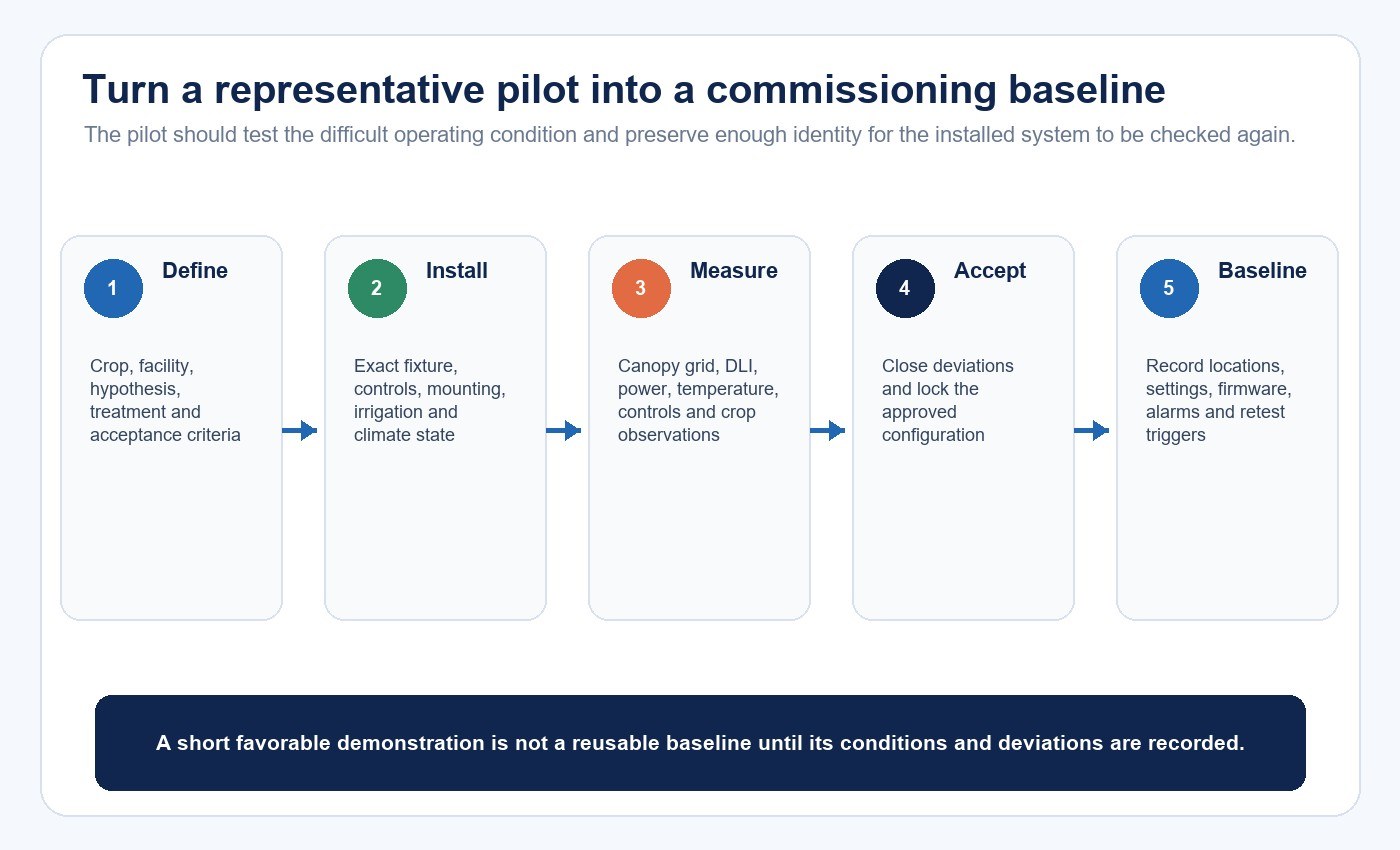
A pilot should answer agronomic, equipment, facility and operational questions before full rollout. Choose a zone that represents the difficult conditions, not only the easiest bay. Include the intended crop, density, mounting, irrigation, climate, fixture, controls and work practices.
Define the hypothesis, comparison treatment, duration, measurement schedule and acceptance criteria before results are seen. Record confounding variables and use randomization or blocking when the experimental question requires it.
| Acceptance layer | Typical evidence | Decision it supports |
|---|---|---|
| Equipment | Ordered model, reports, construction, ratings, control state and installation match | The delivered hardware matches the approved basis |
| Lighting system | Canopy PPFD grid, uniformity, DLI, schedules, sensors, controls and power | The installed system delivers the planned light environment |
| Facility integration | Circuit load, temperatures, airflow, irrigation interaction, alarms and recovery | The system operates safely and predictably in the facility |
| Crop outcome | Agreed timing, morphology, grade, quality, loss and comparison observations | The grower accepts the recipe for the defined crop and condition |
| Operations | Labor, cleaning, maintenance, data capture and failure response | The facility can sustain the result beyond the pilot |
Keep these layers separate. A product report does not establish crop acceptance, and a healthy short demonstration does not establish long-term yield, reliability or economics.
Commission the Installed System
Commissioning should record the fixture model, lot or serial, firmware, location, mounting height, spacing and obstructions. Measure a defined canopy grid at documented control states, then calculate the agreed minimum, average, maximum and uniformity metrics. Record spectrum where channels or recipes vary.
Also verify input power and circuit loading, sensor calibration, zone mapping, schedules, daylight response, overrides, communication loss, power recovery, alarms and data logging. Close each deviation with a documented correction and retest.
Repeat relevant checks when crop height, layout, screens, reflectance, fixture position, recipe, firmware or major climate strategy changes. The indoor grow-light troubleshooting guide provides a symptom-to-test path for later operational problems; commissioning supplies the baseline needed to use it.
Plan Maintenance, Data and Change Control
Define cleaning methods and intervals, access, spares, driver or module replacement, sensor recalibration, firmware support and failure reporting. Dirt, condensation, crop growth, shifted fixtures and sensor drift can change delivered light even when the control screen appears unchanged.
Monitor inputs and outcomes together. Energy data without crop and environment data cannot establish production efficiency; crop data without recipe and facility records cannot explain change. Preserve lot, firmware and configuration traceability when comparing seasons or sites.
Changes to fixtures, drivers, LEDs, optics, mounting, sensors, firmware, recipes, screens or production layout should trigger an impact review. Decide whether the change needs document review, remeasurement, a partial pilot or full recommissioning.
Evaluate Economics With Project Data
Include fixtures, installation, electrical infrastructure, controls, HVAC impact, commissioning, maintenance, financing, downtime and replacement. Model energy from verified operating states and schedules rather than nameplate maximum power alone.
Production benefits should come from the facility’s representative pilot or other defensible crop evidence. Test sensitivity to electricity price, crop grade, cycle time, losses, equipment life and downtime. A single simple-payback number is not a stable conclusion when these inputs remain uncertain.
Horticultural Lighting System Workflow
- Approve the crop, cultivar, stage and production objective.
- Measure crop-plane light, daylight, climate, energy and production baselines.
- Define PPFD, DLI, spectrum, timing, distribution and acceptance criteria.
- Coordinate facility, irrigation, electrical, thermal and operational constraints.
- Compare model-specific fixture and control evidence.
- Complete the layout, infrastructure and control design.
- Run a representative pilot with predetermined measurements.
- Approve equipment, system, facility, crop and operational results separately.
- Commission the installed system and lock approved configurations.
- Monitor maintenance, production and controlled changes.
Teams can review the horticultural and plant-growth lighting solution and a professional horticultural LED flood-light form as discovery starting points. For a model-specific discussion, contact New Lights with the crop brief, canopy drawing, daylight and climate data, production schedule, control requirements and evidence checklist.
Frequently Asked Questions
Is there one best spectrum for horticultural lighting?
No universal spectrum applies to every crop, cultivar, stage, environment and production objective. Use qualified crop evidence and validate the intended commercial system.
Is DLI enough to define a lighting recipe?
No. Intensity, photoperiod, timing, spectrum, distribution and environmental interactions can also change the result. Define acceptable combinations, not only a daily total.
How should daylight be included in a greenhouse design?
Measure or model transmitted daylight at canopy level by zone and season, select the design condition and define how controls deliver the supplemental requirement.
Why is a representative pilot necessary?
It tests crop response, fixture evidence, distribution, controls, facility interaction and operating assumptions together before the cost and risk of full rollout.
Does high PPE guarantee the lowest operating cost?
No. Distribution, utilization, schedule, controls, electricity price, HVAC, maintenance, crop output and system life all affect project economics.
What should trigger recommissioning?
Review changes to crop, canopy, layout, fixture, driver, LEDs, optics, spectrum, firmware, controls, sensors, screens, reflectance, climate strategy or facility configuration.
Editorial Sources
- DesignLights Consortium, “Horticultural Technical Requirements V4.0”: https://designlights.org/our-work/horticultural-lighting/technical-requirements/hort-v4-0/
- DesignLights Consortium, “Technical Requirements for LED-Based Horticultural Lighting V4.0”: https://designlights.org/wp-content/uploads/2025/03/DLC_HORT_Technical_Requirements_V4-0_finalpolicy_031225.pdf
- USDA Natural Resources Conservation Service, “Energy Efficient Lighting System, Additional Considerations for Greenhouse and Nursery Plant Lighting”: https://efotg.sc.egov.usda.gov/api/CPSFile/27741/670_IL_CPS_Energy_Efficient_Lighting_System_2020
- U.S. Department of Energy, “Better Lighting for Agriculture”: https://www.energy.gov/cmei/ssl/better-lighting-agriculture












