


A custom cleanroom luminaire should be specified as part of the room system, not as a standard light with a smooth cover. Begin with the process, cleanliness targets, ceiling and airflow interfaces, cleaning method, maintenance route and lighting criteria. Then connect every requested feature to a controlled drawing, material record, model-specific data, sample check or commissioning result.
The phrase “purification lamp” is easily misunderstood. A luminaire designed for a controlled environment does not automatically purify air, sterilize surfaces or inactivate microorganisms. Those functions require a defined treatment mechanism plus separate efficacy, exposure and safety evidence. This guide therefore focuses on how buyers and project teams can turn a cleanroom brief into a testable luminaire specification.
Define the Environmental Boundary First
Start by identifying the industry, process and consequence of contamination. Pharmaceutical aseptic processing, electronics assembly, optics, food production and medical-device manufacturing may all use controlled spaces, but they do not share one approval route. Record the room classification, whether requirements apply at rest or in operation, occupancy, operating hours, pressure relationship, temperature, humidity, cleaning frequency and maintenance restrictions.
ISO 14644-1:2015 classifies air cleanliness by airborne particle concentration within its scope. It describes the room condition; it does not certify every luminaire installed in that room. ISO 14644-14:2026 provides a methodology for assessing equipment suitability with respect to airborne particle cleanliness, while explicitly leaving matters such as biocontamination, cleanability, material selection and process-specific performance outside its scope. The project owner must add the applicable industry regulations, internal standards and acceptance criteria.
Use this first decision boundary:
| Question | Why it changes the specification | Evidence or decision owner |
|---|---|---|
| What process operates in the room? | Defines contamination consequences and applicable rules | Facility or process owner |
| What room state is assessed? | At-rest and operational conditions can differ | Cleanroom designer or validator |
| What ceiling and pressure boundary is used? | Determines fit, support, sealing and service access | Ceiling and cleanroom contractors |
| Which cleaning agents and methods are approved? | Drives surface, gasket, label and sealant compatibility | Facility cleaning and EHS teams |
| What lighting task must be performed? | Sets illuminance, uniformity, glare, colour and control needs | Lighting designer and user |
| What must be demonstrated before release? | Converts broad expectations into inspection and test gates | Project quality owner |
If any of these inputs is missing, mark it as an open item. Do not allow a room-class label to stand in for the full environmental brief.
Use Product Language That Matches the Function
Name the luminaire by construction and application: for example, recessed cleanroom luminaire, surface-mounted controlled-environment luminaire or sealed serviceable luminaire. Each term should correspond to an actual mounting method, interface drawing and maintenance route.
Do not use “air-purifying,” “sterilizing,” “antimicrobial” or “germicidal” as synonyms for a cleanroom light. A gasket is not a filtration system, and a smooth housing does not establish microbial efficacy. UV-C and other treatment technologies create separate questions about wavelength, dose, exposure control, materials, maintenance and regulatory scope. If the project needs those functions, specify and validate them as a separate system.
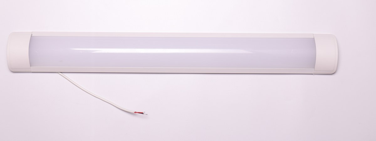
This distinction also prevents keyword overlap. The cleanroom luminaire article owns the specification workflow; a product page such as the surface-mounted LED purification fixture owns the exact available construction and model data. Neither page should imply unsupported room-class certification or disinfection performance.
Freeze the Ceiling, Airflow and Service Interface
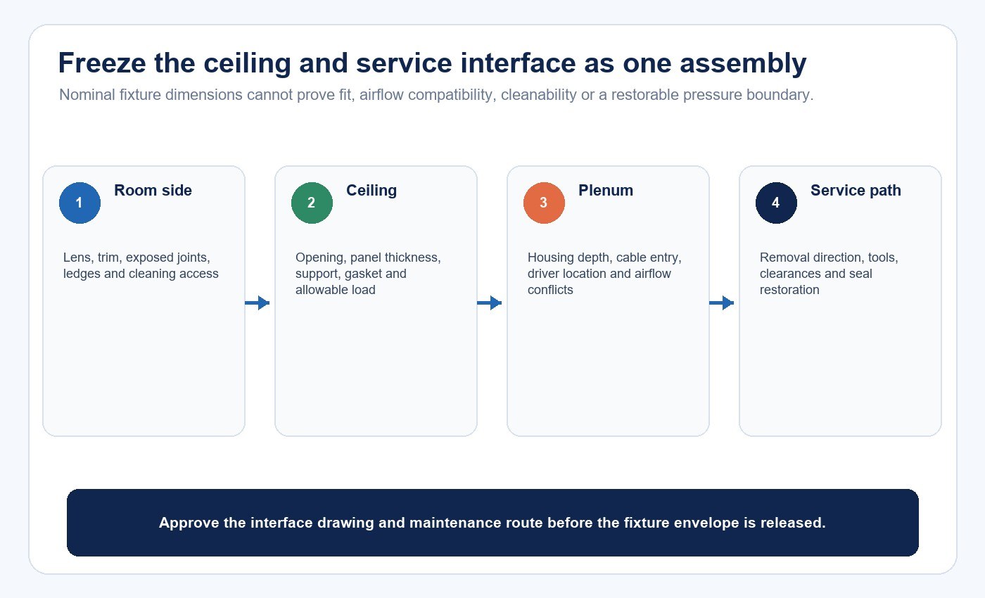
Before approving fixture dimensions, document the ceiling type, module size, panel thickness, opening, support method, allowable load, plenum depth, pressure difference and access direction. Identify whether maintenance takes place from the room side, the plenum or an adjacent panel. A nominal length and width cannot establish fit by themselves.
The reflected ceiling plan should show filters, returns, diffusers, sprinklers, sensors, process tools and access panels. The luminaire may not control airflow, but its depth, projection and service route can still interfere with the designed pattern or create difficult-to-clean zones. Ask the cleanroom designer to approve the layout and relevant sections instead of asking the lighting supplier to infer airflow suitability from a room photograph.
For a custom version, require an interface drawing that shows the ceiling panel, visible trim, room-side face, gasket location, fasteners, housing, cable entry, driver position and removal path. Define which seals are factory-installed and which are completed on site.
Specify Exposed Surfaces and the Cleaning Method Together
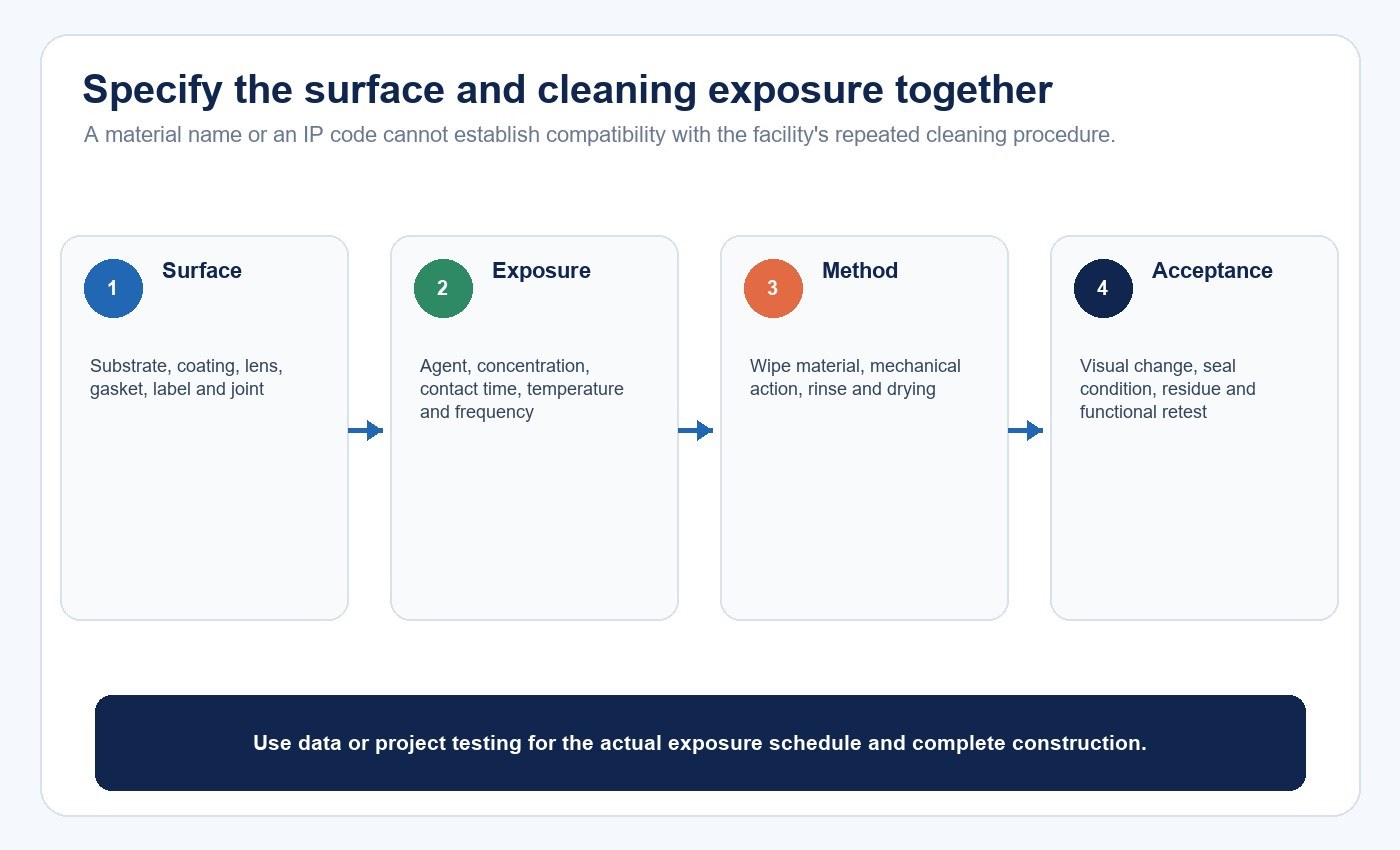
Review every room-side ledge, recess, joint, fastener head, corner, label and transition. The useful question is not whether a product looks “easy to clean,” but whether the facility can reach, wipe, inspect and restore each exposed area using its approved procedure.
List cleaning agents, concentrations, contact times, temperatures, wiping materials, mechanical action and frequency. Occasional water wiping says little about repeated exposure to alcohol, peroxide, chlorine-based chemicals or another site-specific agent. Require material compatibility data or project testing for the actual exposure schedule.
ISO 14644-9:2022 provides a procedure for assessing surface cleanliness by particle concentration. Its scope does not determine process-specific surface suitability, cleaning procedures, material characteristics or microbiological state. Use it only for the question it addresses, then add the project’s chemical, microbial and operational requirements separately.
Control Seams, Penetrations and Site-Applied Materials
Create a seam and penetration register for the lens-to-frame joint, frame-to-ceiling joint, housing seams, cable glands, conduit entries, emergency-test devices, sensors, controls and mounting fasteners. For each item, define its closed condition, retention method, inspection point and service consequence.
An ingress-protection rating can answer a defined water and solid-object ingress question when it is backed by a model-specific report. It is not a complete cleanroom-suitability certificate. The project may still need separate evidence for particle behavior, cleanability, chemical compatibility, pressure effects and maintenance. The IP rating selection guide explains how to keep these evidence scopes separate.
If sealant is applied on site, specify its chemistry, supplier, bead location, surface preparation, cure conditions, inspection criteria and replacement method. A factory test cannot cover an unidentified site sealant applied under uncontrolled conditions.
Build a Material and Configuration Record
The controlled bill of materials should identify the room-side panel, lens, frame or housing, finish, gasket, fasteners, cable-entry components, adhesives and labels. Ask for the property that matters to the project rather than accepting a broad material name. “Stainless steel,” “aluminium,” “tempered glass” and “powder coated” do not define grade, finish, thickness, coating system, edge treatment or chemical compatibility.
Customization can change the evidence boundary. A different diffuser may alter output and glare. A new gasket may change chemical compatibility. A larger housing can affect stiffness and thermal behavior. A relocated driver or sensor can add penetrations and maintenance points. Record each change against a drawing revision and decide whether it requires recalculation, resampling, retesting or regulatory review.
The following matrix keeps customization controlled:
| Configuration field | Freeze in the approved record | Recheck when changed |
|---|---|---|
| Dimensions and mounting | Overall size, opening, support and service direction | Fit, load, sealing and maintenance access |
| Room-side construction | Lens, frame, finish, gasket, fasteners and labels | Cleanability, compatibility and visible joints |
| Electrical system | Voltage, driver, wiring, grounding and cable entry | Safety, EMC, thermal and certification scope |
| Optical system | LED board, output, optics, CCT and CRI | Photometrics, glare, colour and heat |
| Controls and emergency | Protocol, devices, fail state, battery or central supply | Penetrations, commissioning and maintenance |
| Packaging and identification | Model, revision, labels and protected surfaces | Traceability and installation condition |
Classify each requested change as cosmetic, interface, optical, electrical, thermal, contamination-control or regulatory. “Made to order” should mean controlled engineering, not unlimited options without evidence.
Keep Lighting Performance as Its Own Design Workstream
Cleanliness requirements do not replace lighting design. Define the task plane, target illuminance, uniformity, glare limit, vertical illumination where relevant, colour rendering, colour temperature, flicker expectations, dimming range, zoning and emergency behavior. Include mounting height, room reflectance, equipment obstruction and maintenance factors in the calculation.
Request model-specific photometric data for the proposed lens, output and dimensions. A lumen value cannot show distribution or glare, and a family file may no longer represent a custom optical configuration. If the lens, LED board, power or geometry changes, update the calculation and evidence.
Controls require their own interface record. Define protocol, address method, sensor position, power-loss state, communication-loss state, override, commissioning responsibility and cybersecurity ownership where networked systems are used. A controller that looks convenient on a drawing may create a difficult-to-clean penetration or an inaccessible service point.
Check Thermal, Electrical and Emergency Conditions
A sealed or flush housing changes heat transfer and access. Provide ambient temperature, plenum conditions, insulation-contact restrictions, operating hours, supply voltage, frequency, power-quality conditions, circuit arrangement and driver location. Thermal evidence should represent the actual output, enclosure and control state.
List destination-market standards, marks, reports and the responsible approval body. A certified component does not automatically certify the complete custom luminaire. Changes to the driver, wiring, housing, diffuser, emergency module or control device may alter the evaluated construction.
Emergency lighting also needs a defined architecture. Confirm whether the project uses self-contained batteries, a central emergency supply, a generator-backed circuit or another arrangement. Specify duration, charging conditions, indicators, test access, circuit behavior and maintenance. Do not add a battery module late in the project without reviewing thermal, enclosure and certification effects.
Approve a Representative Sample, Not a Near Match
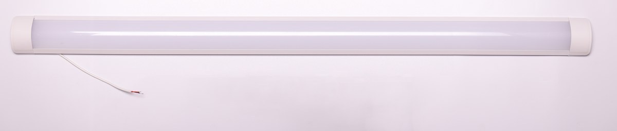
The sample should match the intended production configuration. Check dimensions, mounting interface, exposed joints, finish, seals, fasteners, cable entry, driver access, controls, output, colour, emergency behavior, labels and cleaning access. If the sample uses different materials or electronics, record the deviation and repeat every affected check before release.
Use a written inspection plan with measured values and pass/fail criteria. Photographs support traceability but cannot replace measurements, drawings or reports. For critical interfaces, assemble a mock-up with the actual ceiling or mounting components and demonstrate the removal path.
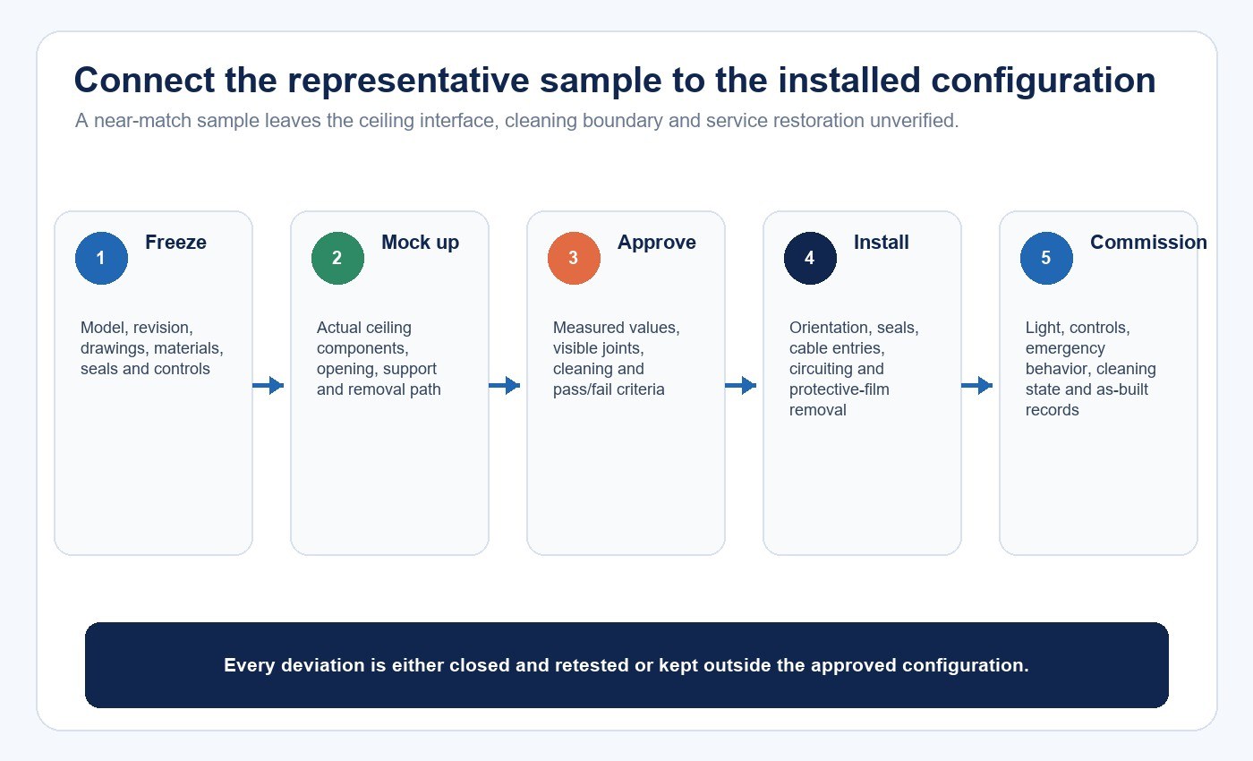
The LED lighting sample evaluation checklist can be adapted to the cleanroom configuration. Add project-specific checks for room-side joints, approved cleaners, seal condition, pressure boundary and post-service restoration.
Commission the Installed Configuration
Commissioning must connect the approved sample to the real installation. Confirm model and revision, orientation, support, ceiling seals, cable entries, protective-film removal, cleaning condition, circuiting, controls, emergency operation, measured light levels and any required environmental checks.
Close deviations through change control. A substituted sealant, enlarged opening, relocated driver or unsealed service point can break the connection between the installed condition and the approved evidence. The closeout package should include as-built drawings, configuration records, test results, cleaning instructions, spare-parts information and maintenance procedures.
Maintenance should preserve the boundary over time. Define inspection frequency, permitted cleaners, lens and gasket replacement, closure checks, driver access and post-maintenance verification. The New Lights factory and manufacturing overview provides context for discussing configuration control, sample review and production documentation with the project team.
Prepare an Evidence-Based RFQ
Separate buyer inputs from supplier outputs. Buyer inputs should include the process and room state, ceiling and airflow drawings, environmental conditions, cleaning procedure, lighting targets, controls, emergency architecture, destination market and acceptance tests.
Supplier outputs should include the exact model and revision, configuration matrix, dimensional and interface drawings, bill of materials, photometric and electrical data, relevant reports, installation instructions, cleaning limitations, service procedure, sample plan and unresolved-items list. Each report should identify the tested configuration and scope.
Use this release sequence:
- Freeze the environmental and room interface brief.
- Approve the configuration matrix and drawings.
- Map each requirement to evidence or a planned test.
- Review a representative sample and ceiling mock-up where needed.
- Release production only after deviations are closed.
- Verify installation and preserve the as-built record.
To discuss a custom cleanroom lighting project, contact New Lights with the room brief, ceiling details, cleaning procedure, lighting criteria, control requirements and evidence list. The team can then identify what an existing linear batten platform supports, what requires controlled engineering and what still needs project validation.
Frequently Asked Questions
Is a cleanroom luminaire the same as a purification lamp?
No. A cleanroom luminaire provides lighting within a controlled environment. “Purification lamp” can imply air cleaning or disinfection, which requires a defined treatment mechanism and separate efficacy and safety evidence.
Does an ISO cleanroom class certify the luminaire?
No. ISO 14644-1 classifies airborne particle cleanliness within its scope. Equipment suitability and project acceptance require separate assessment against the intended environment, operating condition and applicable evidence.
Is a sealed light automatically suitable for a cleanroom?
No. Sealing addresses only part of the interface. The project may also need evidence for ceiling fit, particle behavior, surface cleanability, chemical compatibility, maintenance access, thermal performance, electrical safety and photometric performance.
What information is needed before customization starts?
Provide the process, room classification and state, ceiling and airflow drawings, cleaning agents and procedure, environmental conditions, lighting targets, controls, emergency architecture, destination market and required acceptance tests.
Can output, CCT and controls be customized independently?
Not always. Changes to the LED board, driver, optics, output or controls can affect photometrics, thermal behavior, electrical evidence and certification scope. Review the combined configuration rather than approving each option in isolation.
Should UV-C be included in the same specification?
Not by default. UV-C introduces exposure, dose, efficacy, material, control, maintenance and regulatory questions. If it is required, specify and validate it as a separate system instead of treating it as an inherent cleanroom-light function.
Editorial Sources
- ISO, “ISO 14644-1:2015 — Cleanrooms and associated controlled environments — Part 1: Classification of air cleanliness by particle concentration”: https://www.iso.org/standard/53394.html
- ISO, “ISO 14644-14:2026 — Cleanrooms and associated controlled environments — Part 14: Assessment of suitability for use of equipment by airborne particle concentration”: https://www.iso.org/standard/91615.html
- ISO, “ISO 14644-9:2022 — Cleanrooms and associated controlled environments — Part 9: Assessment of surface cleanliness for particle concentration”: https://www.iso.org/standard/76889.html












