


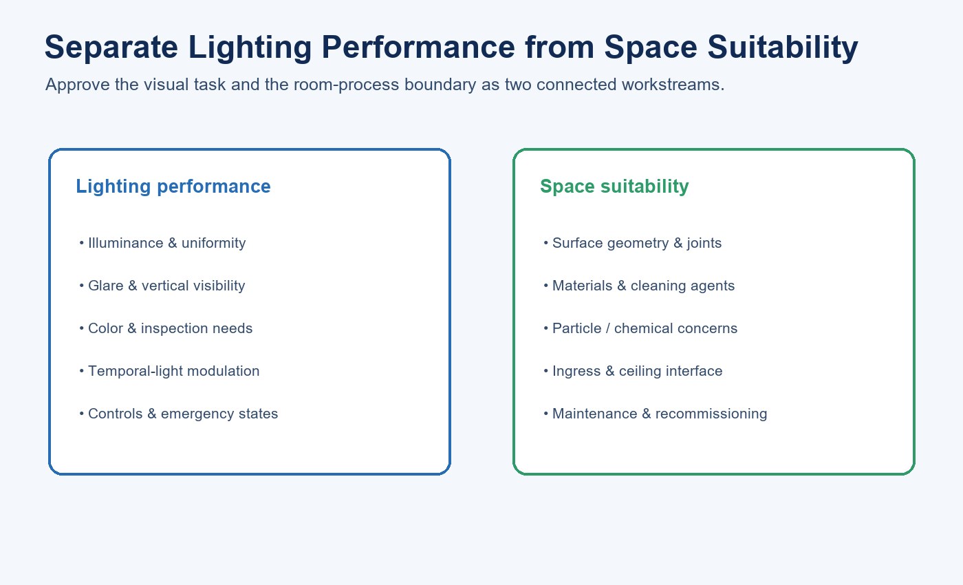
Lighting for a clean or controlled space has two jobs. It must provide the required visual conditions, and its construction must fit the room’s contamination-control and cleaning practices. A product name such as “purification lamp” does not prove either job, and it certainly does not prove that the light purifies air.
The useful selection process separates illumination from cleanliness. First define illuminance, uniformity, glare, color and temporal-light requirements. Then evaluate surfaces, joints, materials, connectors, ingress, cleaning compatibility, particle shedding and maintenance. Any air-treatment or antimicrobial function must be identified and tested as a separate subsystem.
| Workstream | Define | Approval evidence |
|---|---|---|
| Visual task | Illuminance, uniformity, glare, color and inspection needs | Photometric calculation and mockup |
| Temporal light | Driver, supply, controls and camera sensitivity | Product-level waveform data |
| Cleanability | Surfaces, joints and cleaning procedure | Representative cleaning-cycle review |
| Materials | Exposed plastics, metals, labels and connectors | Compatibility and process assessment |
| Maintenance | Access, debris control and recommissioning | Approved service method |
Clarify What the Product Actually Is
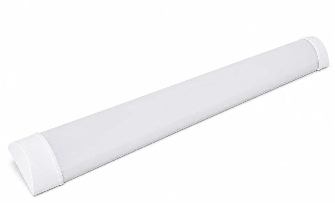
The current New Lights Surface-Mounted LED Purification Fixture is an enclosed 75 × 22 mm linear fixture with an integrated LED board behind a continuous cover and PC end caps. Metal clips retain it against the mounting surface. The historical product name describes the fixture family; it does not add air-treatment, ultraviolet or germicidal functionality.
The catalogue identifies four model rows: XGYPL102-E18, XGYPL103-E24, XGYPL104-E36 and XGYPL105-E40. Their listed lengths are 600, 900, 1200 and 1500 mm, with rated powers of 18, 24, 36 and 40 W. The bracketed 702/202-style references require clarification before they are used as variant identifiers.
None of the retrieved product material documents filtration, ionization, photocatalysis, UV-C, antimicrobial output or another air-purification module. Treat it as a linear lighting candidate for selected indoor spaces, not an air-cleaning device.
Define the Room and Process Requirement
“Clean space” can describe many environments, from an easy-clean hospital corridor to a classified manufacturing room. Record the actual classification, regulatory framework, process sensitivity and operating state. Identify whether the concern is airborne particles, surface particles, chemical contamination, microorganisms or ordinary housekeeping.
ISO 14644-1 classifies air cleanliness by airborne particle concentration. Other parts of the ISO 14644 family address equipment suitability, surfaces and chemical cleanliness. A lighting fixture does not inherit a room classification merely because it is installed there. The project team must assess whether its materials, geometry and operation are suitable for the defined environment.
Also map the ceiling system, room pressure strategy, airflow pattern, maintenance access and cleaning method. A fixture that is acceptable in a corridor may not be appropriate above an exposed pharmaceutical process.
The commercial lighting specification guide provides a broader project framework for visual tasks, controls, maintenance and procurement evidence.
Set Visual Performance Targets
Define maintained illuminance at the task plane, uniformity, glare limit, color rendering, correlated color temperature and any special inspection needs. Use the applicable project and workplace criteria rather than one generic lux target.
Request an IES or LDT photometric file for the exact configuration. Model the fixture layout with room reflectances, mounting height, spacing and obstructions. The catalogue’s statement about lighting in five directions and avoiding dark areas is a design description, not proof of uniformity in every room.
Check vertical as well as horizontal illumination where operators inspect equipment faces, shelving or walls. Highly reflective clean-space surfaces can increase glare. A large luminous surface may help visual comfort, but the actual luminance distribution and viewing angles still need evaluation.
| Photometric input | Record | Decision supported |
|---|---|---|
| Task plane | Height, orientation and work area | Maintained illuminance target |
| Room geometry | Dimensions, reflectance and obstructions | Fixture count and spacing |
| Distribution | IES/LDT file for exact model | Uniformity and vertical visibility |
| Glare | Method, viewing positions and limit | Visual comfort and inspection accuracy |
| Controls | Switching, CCT, dimming and emergency state | Every operating condition |
Verify Flicker Rather Than Relying on a Label
The catalogue refers to a no-light-flickering IC driver, but it does not provide a waveform or test conditions. Ask for product-level temporal-light-modulation data for the offered driver and supply. Include relevant operating states such as CCT selection, dimming and linked operation.
A phone camera can screen for obvious banding but cannot establish compliance. A defensible review identifies the waveform, frequency, modulation and application-relevant metrics under defined electrical conditions.
This matters in spaces with rotating equipment, machine vision, inspection cameras or sensitive tasks. The acceptance threshold should follow the application, not a broad “no flicker” phrase.
Inspect Surface Geometry and Joints
Easy cleaning begins with accessible surfaces and controlled joints. Review the cover-to-body seam, end caps, switches, connectors, mounting interfaces and any label recesses. Sharp steps, open gaps and exposed cavities can trap residue.
Obtain an exploded drawing and photographs of the assembled ends. Confirm how the PC cover and end caps are retained and whether field linking leaves exposed openings. If unused connector ports require caps, include them in the approved configuration.
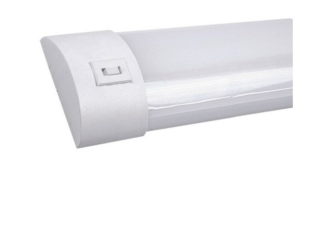
Smooth appearance alone does not prove cleanability. The team should test the prescribed wipe or wash method and inspect whether residue remains around joints and controls.
Check Materials and Cleaning Compatibility
Record every externally exposed material, including plastics, metals, coatings, seals, adhesives, labels and connector parts. Compare them with the facility’s cleaning and disinfection agents, concentrations, contact times and temperatures.
Repeated exposure can cause stress cracking, discoloration, swelling, corrosion or loss of seal compression. A one-time visual wipe is weak evidence. Use compatibility data or representative cycle testing where the room has a demanding cleaning protocol.
Chemical compatibility is separate from particle cleanliness. A material may shed little yet react with a cleaning agent, or clean easily while emitting a chemical that matters to a sensitive process.
Assess Particle and Chemical Suitability
ISO 14644-14 provides a methodology for assessing equipment suitability with respect to airborne particle cleanliness. A project claiming cleanroom suitability should request relevant evidence rather than equating a product category name with conformity.
Potential sources include moving or flexing plastic interfaces, exposed foam, labels, cable jackets, connector wear and debris generated during maintenance. Consider the equipment in operation and during service, not only as a new static sample.
Use the LED product compliance document checklist to separate market-access files from room-specific particle, material and process evidence.
Where airborne or surface chemical contamination matters, define the substances and thresholds. Request material and emission evidence that matches the process. Do not use “purification” as a substitute for these assessments.
Review Ingress and Room-Pressure Interfaces
Determine whether the fixture is surface mounted, recessed or integrated into a ceiling boundary. A room-pressure strategy may require controlled penetration details around wiring and mounting. The fixture’s own enclosure rating does not automatically seal the building interface.
Confirm the product’s ingress rating, if any, for the exact model. Match it to the cleaning process and room exposure. Do not infer washdown suitability from a smooth cover or a hospital-corridor image.
Coordinate cable entry and connector placement with the ceiling and airflow design. Avoid modifications that introduce uncontrolled holes or hidden dirt traps.
Validate Linking and Electrical Layout
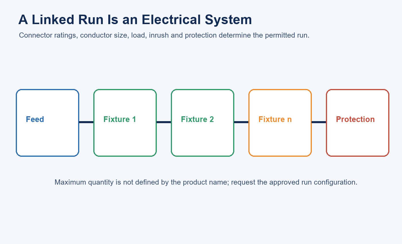
The catalogue states that multiple connections are supported, but the retrieved data does not define the maximum linked run. Request connector voltage and current ratings, conductor size, feed location, maximum fixture count, inrush limits and protective-device guidance.
| Linked-run variable | Supplier record | Site verification |
|---|---|---|
| Connector | Voltage, current and mating cycle | Correct parts and full engagement |
| Conductors | Size, temperature and routing | Installation matches the approved run |
| Fixture load | Exact length, power and driver | Total steady load |
| Inrush | Per-driver data and protective-device basis | Run-level switching behavior |
| Controls | Feed point and control topology | Intended grouping and fault isolation |
The T5 integrated fixture linking guide explains the run-level calculation logic; apply it only after obtaining this product’s own connector and driver values.
Keep the linked configuration traceable. Combining different lengths, wattages, CCT versions or driver options can change circuit loading. Verify whether controls operate one fixture or the whole run and whether a failed unit can be replaced without opening adjacent clean boundaries.
Plan cable routing and disconnection so maintenance does not release debris over the process area. If work must occur from inside the room, define isolation, cleaning and recommissioning steps.
Build a Representative Mockup
Install a sample in the actual or representative ceiling. Verify illuminance, uniformity, glare, visual appearance, switching and flicker. Run the specified cleaning cycle and inspect surfaces, joints and labels. Check connector access and replacement steps.
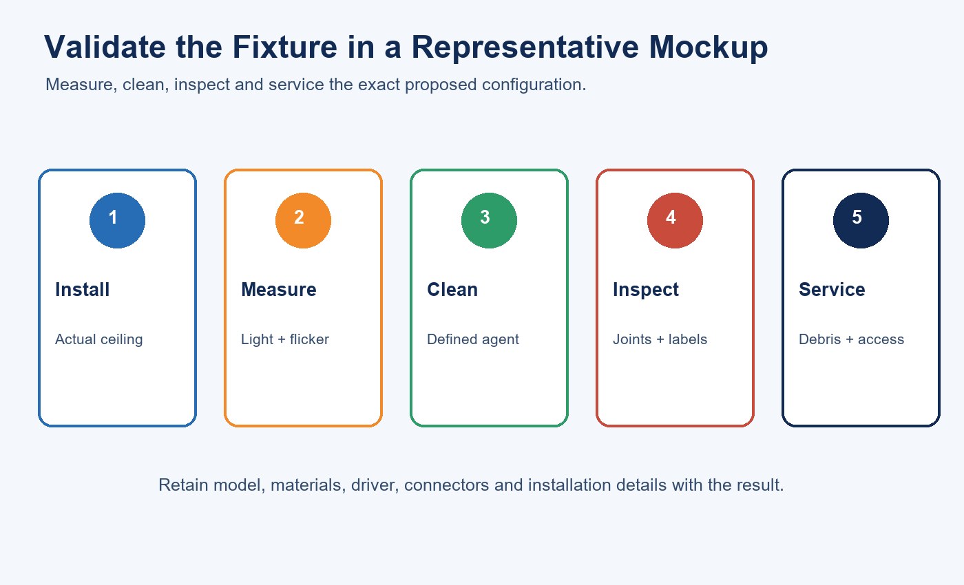
| Mockup stage | Measure or observe | Acceptance output |
|---|---|---|
| Installation | Ceiling fit, clips, wiring and openings | Reproducible mounting detail |
| Lighting | Illuminance, uniformity, glare and waveform | Task-performance record |
| Cleaning | Agent, concentration, contact time and method | Surface and joint condition |
| Inspection | Residue, cracking, labels and connectors | Material and cleanability decision |
| Service | Access, debris, isolation and recommissioning | Approved maintenance procedure |
Use the LED lighting sample evaluation checklist to preserve the exact model, setup and result. For supplier controls, continue with the lighting supplier factory audit checklist.
For higher-control environments, include the fixture in the equipment-suitability and room-commissioning process. Record the exact model, materials, driver, connectors and installation method. A successful mockup supports that configuration, not every product carrying the same family name.
For a bounded review, provide the room classification, task and lighting targets, ceiling detail, cleaning agents, material restrictions, connector layout and maintenance process when you contact New Lights.
The New Lights factory and manufacturing capability page outlines the wider configuration and production context.
Maintain the Clean-Space Configuration
Create approved cleaning instructions and inspection intervals. Look for cracked covers, loose end caps, damaged connectors, residue around switches, label deterioration and internal contamination. Replace parts only with approved materials.
After service, restore caps, seals and mounting details. Clean the work area and perform any required particle or operational verification. Record configuration changes so later reviews can distinguish the original qualified sample from modified installations.
Use the lighting maintenance and spare-parts planning guide to keep approved end caps, connectors, clips and drivers tied to the installed configuration.
FAQ
Does an LED purification lamp clean the air?
Not unless it contains a documented and tested air-treatment system. The retrieved New Lights product material describes lighting components only.
What does 2835 SMD mean?
It identifies an LED package format used as the light source. It does not prove purification, cleanroom suitability, energy performance or flicker results.
Can this fixture be called cleanroom certified?
Not from the current evidence. Suitability must be assessed against the room’s particle, chemical, cleaning and process requirements.
Does five-direction light guarantee no dark areas?
No. Confirm room-level illuminance and uniformity with photometric data, layout calculation and a mockup.
What limits a linked fixture run?
Connector ratings, conductor size, fixture load, inrush, feed arrangement and protective devices. Obtain an approved maximum-run specification.
What evidence should be checked before approval?
Review photometry, flicker data, drawings, materials, cleanability, chemical compatibility, ingress, connector limits and any required particle or chemical suitability assessment.
Editorial Sources
- New Lights, “LED Linear Fixtures” catalogue: https://new-lights.com/new-lights/2024/12/06/ledlinearfixtures.pdf
- New Lights, “LED Purification Lamps”: https://www.new-lights.com/product/led-linear-fixtures/led-purification-lamps.html
- ISO, “ISO 14644-1:2015”: https://www.iso.org/standard/53394.html
- ISO, “ISO 14644-14:2026”: https://www.iso.org/standard/91615.html












