


A linkable T5 fixture is a small electrical and mechanical system, not an unlimited chain of light bars. The permitted run depends on the exact fixture model, rated input, feed cable, connectors, switching device, inrush behavior, protection, installation environment and manufacturer instructions. Plan every run before ordering, then verify the selected fixture and accessories as one system.
Define Each Run on the Drawing
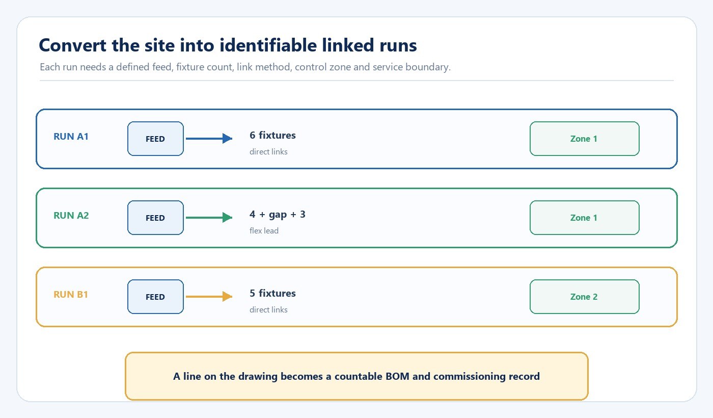
Give every run an identifier such as A1, A2 or B1. Record the fixture length and quantity, total rated input, feed end, linking direction, connector type, mounting method, control zone and service boundary. Show gaps where a flexible lead is needed instead of a direct coupler. A dimensioned elevation is often clearer than a ceiling plan for shelves, cabinets and production benches.
| Drawing field | What to record | Decision it supports |
|---|---|---|
| Run geometry | Fixture lengths, quantities, corners and gaps | Product and accessory quantities |
| Power entry | Feed location, cable route and supply point | Electrical design, cable visibility and access |
| Link method | Direct coupler or flexible lead | Alignment around joints and obstructions |
| Control zone | Switch, sensor or controller serving the run | Operating behavior and commissioning |
| Mounting | Clips, screws, substrate and access | Mechanical security and maintenance |
The drawing should identify where one run stops even if another run begins nearby. This prevents installers from extending a chain because the connector fits while overlooking the verified electrical limit or control strategy.
Calculate the Run From the Lowest Verified Limit
Start with the exact fixture input and quantity:
Total run input power = fixture quantity × rated fixture input power
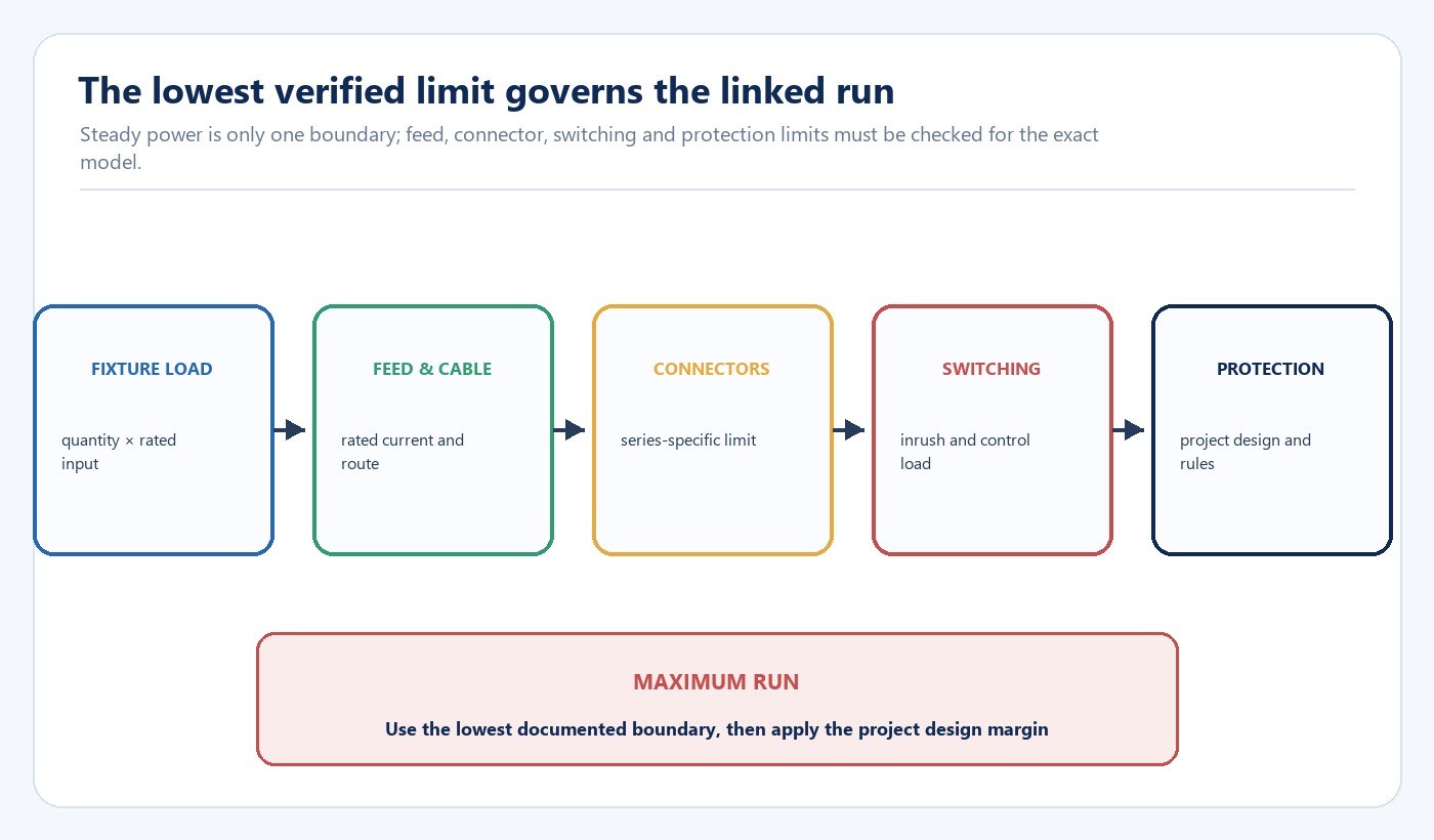
Then compare the result with every other boundary in the chain. The feed cable and connector ratings, model-specific maximum linking quantity, switching device, protective device and project design may impose a lower limit. Drivers can also draw short inrush current at switch-on, so a group that appears acceptable by steady-state power may not be suitable for a particular switch, relay or control output.
Do not calculate the maximum quantity by dividing circuit capacity by fixture wattage and treating the result as a product instruction. The fixture manufacturer or supplier should identify the supported run limit and the conditions behind it. The electrical designer or qualified installer then checks the supply, protection, wiring method and local requirements for the actual project.
Worked planning example
Suppose a drawing calls for twelve fixtures on one shelf line. The arithmetic load may be below the branch-circuit capacity, but the verified product instruction may allow fewer fixtures per feed, or the selected control output may have a lower inrush boundary. Split the shelf into two identified runs when any documented limit requires it. The correct result is the lowest applicable limit, not the largest number produced by one calculation.
Verify the Exact Fixture and Accessory Family
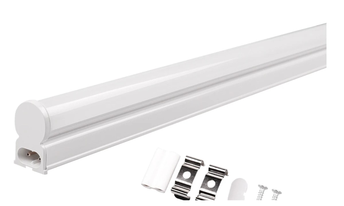
Integrated fixtures from different series can look similar while using incompatible plugs, direct couplers, flexible leads, mounting clips or end arrangements. Freeze the complete accessory set with the approved sample: power lead, direct coupler, flexible link lead, clips, screws and end caps where applicable. Record the exact model and option references instead of ordering accessories by appearance.
The product image above has been source-cropped to show the fixture and supplied accessories without the unused catalogue canvas. It is displayed at a restrained desktop width so it supports identification without displacing an entire screen of article content.
Plan Feed Direction, Corners and Service Access
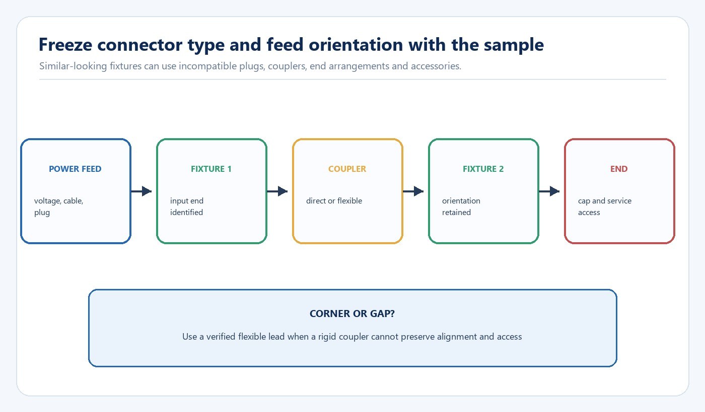
Identify the input end and linking direction on the drawing. At corners, structural joints or removable shelving, a verified flexible lead may be preferable to a rigid coupler. Where a visible cable is unacceptable, define the concealment route and bend space before production quantities are ordered.
Leave enough access to disconnect one fixture without dismantling the entire run. The first and last units should remain reachable for testing, and any switch or sensor built into the series needs a defined orientation. A connector that mechanically fits is not evidence that its electrical rating, polarity or wiring arrangement matches another series.
Check Mounting, Thermal Conditions and Light Distribution

The mounting substrate must hold the specified clips and remain stable under expected temperature, vibration and cleaning. Confirm whether the exact fixture can be installed in a recess, near heat-producing equipment or against a particular material. Do not cover the housing or driver area unless the product instructions allow it.
U.S. Occupational Safety and Health Administration standard 1926.405 provides a U.S. construction reference that fixture wires must suit the voltage, temperature and location of use and that fixtures must be securely supported. It is not a universal design instruction: the exact product instructions, project design and applicable local electrical rules govern the installation.
For commercial and retail lighting applications, check that the shelf edge does not hide the light and that glossy merchandise does not create distracting reflections. For workbenches, review useful illuminance and uniformity across the task area. A representative sample run can expose shadow lines, connector visibility, cable-management problems and access conflicts that a product image cannot show.
Coordinate Control and Maintenance Zones
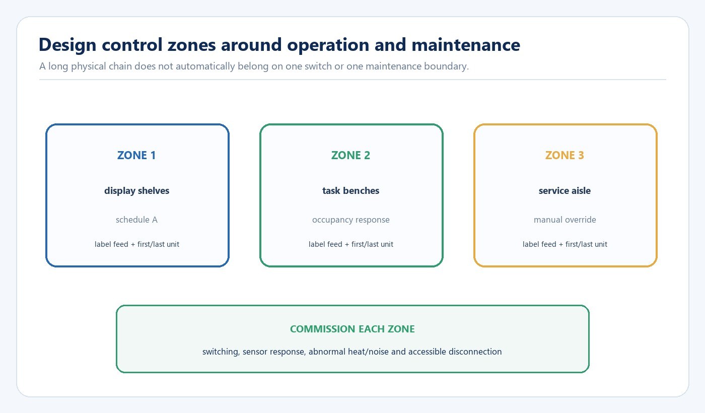
One physical line of fixtures does not automatically belong on one switch. Separate display bays, aisles or work areas when they have different schedules, occupancy patterns or manual-override needs. Sensors, timers and building controls must be checked against the driver load, switching frequency and expected operating states.
The U.S. Department of Energy Lighting Controls Solutions resources emphasize defining control objectives, system capabilities and documentation together. Apply that principle at run level: identify which control serves each feed, what normal and override behavior should occur, and how the result will be commissioned. The LED driver, dimming and control compatibility guide provides a broader compatibility framework.
Label each feed and run, keep the wiring diagram and accessory list with the as-built record, and store spare fixtures and connectors from the approved series. A replacement should not depend on someone recognizing an unlabelled connector years later.
Build the RFQ and Commissioning Record
| RFQ or release item | Required detail | Acceptance check |
|---|---|---|
| Fixture | Exact model, length, input, CCT and quantity by run | Quote and sample match the drawing |
| Supply | Voltage, frequency, feed cable and protection | Reviewed for the project location |
| Linking | Maximum quantity, couplers, flexible leads and orientation | Supported by the exact series documentation |
| Controls | Switch, sensor or controller and zone behavior | Tested with representative load |
| Mounting | Substrate, clips, screws, clearance and access | Sample run remains secure and serviceable |
| Commissioning | Switching, abnormal heat/noise, security and labels | Results recorded by run identifier |
Before volume release, use the LED lighting sample evaluation checklist to reconcile the received sample with the quotation and drawing. For production coordination and change-control evidence, review New Lights’ factory and manufacturing capabilities. Send the dimensioned run schedule and accessory list through the contact page when requesting a project review.
Frequently Asked Questions
How many T5 integrated fixtures can be linked together?
There is no universal quantity. Use the maximum stated for the exact model and verify the feed, connectors, switching device, inrush behavior, protection and local project requirements. The lowest applicable boundary governs.
Can fixtures from different T5 series use the same connector?
Do not assume so. Similar connector shapes can have different dimensions, ratings, polarity or wiring arrangements. Approve the exact fixture and accessory family together.
Should a corner use a rigid coupler or flexible lead?
Use the connector type approved for the series and suited to the geometry. A flexible lead is often more practical where alignment, movement or service access makes a rigid coupler unsuitable.
What should be checked on a sample run?
Check fixture identity, accessories, mounting security, cable appearance, light distribution, switching and sensor behavior, abnormal heat or noise, labels and the ability to disconnect and replace a unit.
Editorial Sources
- U.S. Occupational Safety and Health Administration, “1926.405 — Wiring methods, components, and equipment for general use”: https://www.osha.gov/laws-regs/regulations/standardnumber/1926/1926.405
- U.S. Department of Energy, “Lighting Controls Solutions”: https://www.energy.gov/cmei/ssl/lighting-controls-solutions












