A tubular LED lamp driver must match the LED board, input supply, tube construction, controls and intended operating environment. Wattage alone cannot establish compatibility. The useful selection question is whether one defined driver can regulate the intended LED load across production, temperature and supply variation while meeting the project’s safety and performance requirements.
Start with the complete lamp architecture. Record the LED-board operating window, market voltage, wiring method, enclosure, dimming requirement and acceptance criteria before choosing a circuit or supplier. This prevents a nominally suitable driver from becoming the constraint during startup, hot operation, low-level dimming or abnormal conditions.
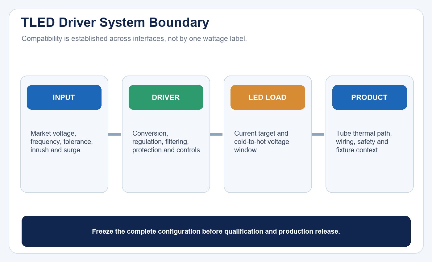
Treat the driver as one part of the complete tube system. Each interface needs a defined operating range and verification method.
The LED tube versus fluorescent tube guide explains the wider retrofit architectures. This article focuses on selecting and qualifying the LED power-conversion stage inside or paired with a TLED system.
Define the Driver’s Job Before Selecting It
An LED driver converts and regulates electrical power for an LED package, array or lamp. Depending on the topology, it may also provide input filtering, power-factor correction, surge handling, dimming interfaces, fault response and thermal protection.
That description does not imply that every feature is present in every driver. Build a requirements sheet that separates mandatory functions from optional ones. A direct-wire tube, ballast-compatible tube and external-driver Type C system place different electrical and installation boundaries around the driver.
| Requirement group | Define before selection | Evidence to review | Common shortcut to avoid |
|---|---|---|---|
| LED load | Current target and complete voltage window | LED-board data and assembled-lamp measurements | Selecting by watts only |
| Input | Voltage, frequency, tolerances and disturbances | Test report at relevant conditions | Treating nominal voltage as the full range |
| Construction | Internal or external driver, space and thermal path | Drawing, BOM and thermal measurements | Reviewing the driver on an open bench only |
| Controls | Switching, dimming method and operating range | Compatibility data and representative circuit test | Assuming a shared protocol label proves behavior |
| Safety | Isolation, accessible parts and wiring architecture | Applicable certification and instructions | Treating the driver independently from the tube |
Match the LED-Board Operating Window
The driver’s output must cover the LED string across cold start, stabilized operation, tolerance and aging-related change. Define the LED package, series-parallel arrangement, target current and forward-voltage distribution. One fixed voltage per LED or one universal current is not a valid design rule.
Forward voltage changes with device selection, current, temperature and production distribution. If the string voltage rises above the driver’s compliance range, the driver may not reach the intended current. If it falls outside the supported lower range, regulation or protection behavior may change. The design therefore needs margin around the expected operating envelope rather than a single calculated point.
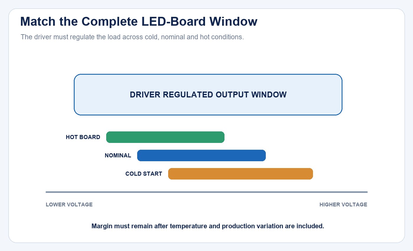
The LED-board range must remain inside the driver’s regulated output window under the conditions that matter to the product.
Verify the assembled system at cold startup, nominal operation and the defined hot condition. Record current regulation, light output, startup overshoot and any protection cycling. Use the LED lighting sample evaluation checklist to keep samples, configuration and acceptance criteria traceable.
Specify the Input and Power-Quality Boundary
Define the destination markets, nominal supply, frequency and allowed variation. Then decide which disturbances require evidence: undervoltage, overvoltage, repeated switching, inrush, surge, harmonics and conducted or radiated emissions.
Real power, apparent power, power factor, harmonic distortion and efficiency describe different behavior. A high power factor does not prove high efficiency or low flicker. The flicker, power factor and THD buyer checklist shows how to request those measurements without substituting one metric for another.
| Metric or event | What it reveals | What it does not prove | Useful test boundary |
|---|---|---|---|
| Efficiency | Driver loss at a stated operating point | Installed temperature or lifetime | Input/output power after stabilization |
| Power factor | Relationship of real and apparent power | Harmonic spectrum or light modulation | Defined voltage, frequency and load |
| THD | Harmonic content of input current | Efficiency or flicker | Same configuration used for compliance review |
| Inrush | Short-duration energization current | Repetitive switching endurance | Minimum and maximum circuit quantity |
| Surge response | Behavior under a defined transient | Immunity to every site disturbance | Waveform, level, polarity, coupling and pass criterion |
Do not size switching devices or controls from steady-state watts alone. Multiple electronic drivers can create a different inrush and repetitive peak-current condition from one load with the same total wattage.
Check Thermal Performance in the Complete Tube
Driver losses become heat inside a narrow enclosure. The result depends on topology, component placement, tube materials, LED-board heating, orientation, ambient temperature and whether the host fixture traps heat.
Identify the driver temperature measurement point, limit and test condition. Measure the complete tube after stabilization in a representative fixture or enclosure. An open-bench driver temperature cannot establish the installed thermal margin.
Thermal review should connect temperature to the actual component ratings and loading. Electrolytic capacitors may be important, but semiconductors, magnetics, resistors, solder joints and protection parts also need appropriate selection and derating. The streetlight driver reliability guide covers the same evidence chain in a harsher outdoor luminaire context.
Define Protection and Recovery Behavior
List the abnormal conditions relevant to the product: open output, short circuit, overload, excessive temperature, surge and supply outside the permitted range. For each one, specify both the protective action and the recovery behavior.
A driver may shut down, limit output, enter a repeating restart cycle or latch until power is removed. Those behaviors affect safety, visible symptoms and field diagnosis. Repeated flashing, for example, may indicate protection cycling rather than a failed LED package.
Protection should be coordinated with the complete product and electrical environment. A single universal surge level is not suitable for every indoor, industrial or outdoor circuit. Reports should identify the waveform, level, polarity, coupling path, sample identity and pass criterion.
Separate Safety, Isolation and Installation Architecture
Determine whether the driver is isolated or non-isolated and how that choice affects accessible parts, creepage, clearance, dielectric testing, insulation and installation instructions. Review safety at the lamp-system level rather than treating the internal driver as a standalone approved object.
For retrofit tubes, record whether the product operates through a compatible fluorescent ballast, receives line voltage after a defined conversion or uses an external LED driver. Socket arrangement, single- or double-ended input, fixture labels and replacement instructions are part of the product boundary.
The LED product compliance document checklist helps distinguish product identity, applicable standard, report scope and market documentation. Electrical measurements and modifications should be performed only by qualified personnel under approved procedures.
Verify Flicker and Light Stability
Output filtering, control method and load point influence temporal light modulation. Check the exact metrics required for the market or application and record the operating condition behind each result.
Test full output and any required dimmed states. Include relevant supply variation, warm-up and minimum-load conditions. Observe startup delay, overshoot, dropout, cycling, shimmer and acoustic noise. A phone-camera pattern can help document a symptom, but it is not a calibrated measurement.
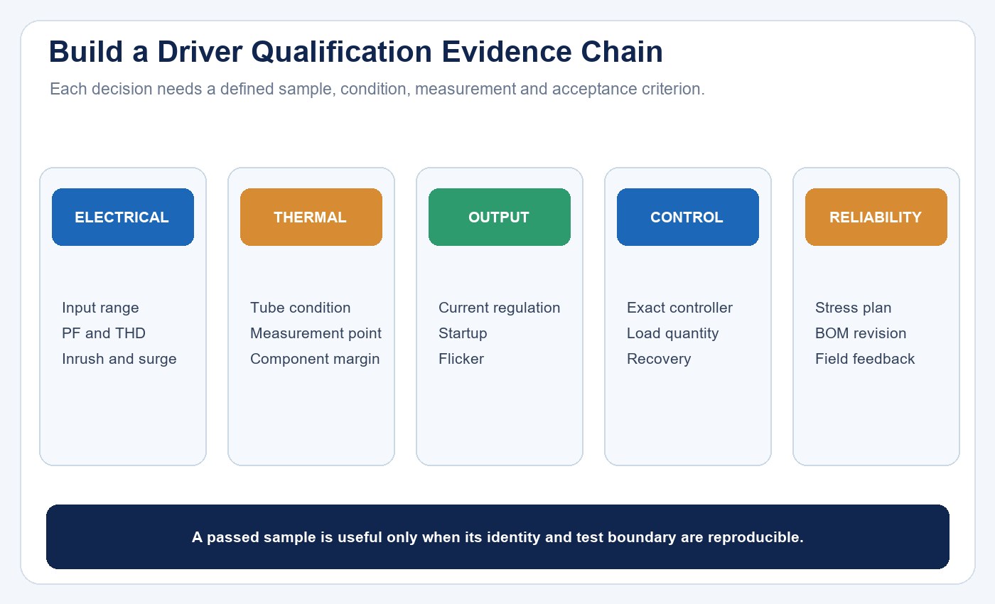
A qualification package connects every decision to a defined sample, condition, measurement and acceptance criterion.
Treat Dimming as a System Compatibility Task
Not every TLED is dimmable. When control is required, define the method, compatible devices, minimum usable output, off behavior, curve, transitions and circuit quantity. A label such as phase-cut, 0–10 V or DALI does not prove compatibility with every controller carrying the same term.
Test the exact driver, LED load, controller, supply and wiring topology together. Check startup, pop-on, dropout, flicker, noise, transitions and recovery after power interruption. The LED driver, dimming and control compatibility guide provides the project-level commissioning sequence.
Qualify Reliability With an Evidence Chain
Reliability is not a component slogan or a conversion from LED package lumen maintenance. Define the failure criteria for the complete lamp, then connect operating temperature, component loading, protection, manufacturing controls and test duration to that definition.
| Evidence layer | Question it should answer | Weak substitute |
|---|---|---|
| Design review | Are topology, ratings and derating appropriate? | A generic component brand list |
| Thermal validation | What temperatures occur in the assembled tube? | Open-bench operation |
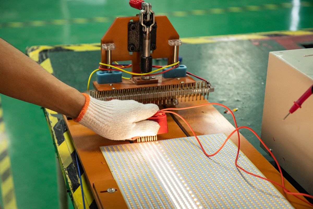
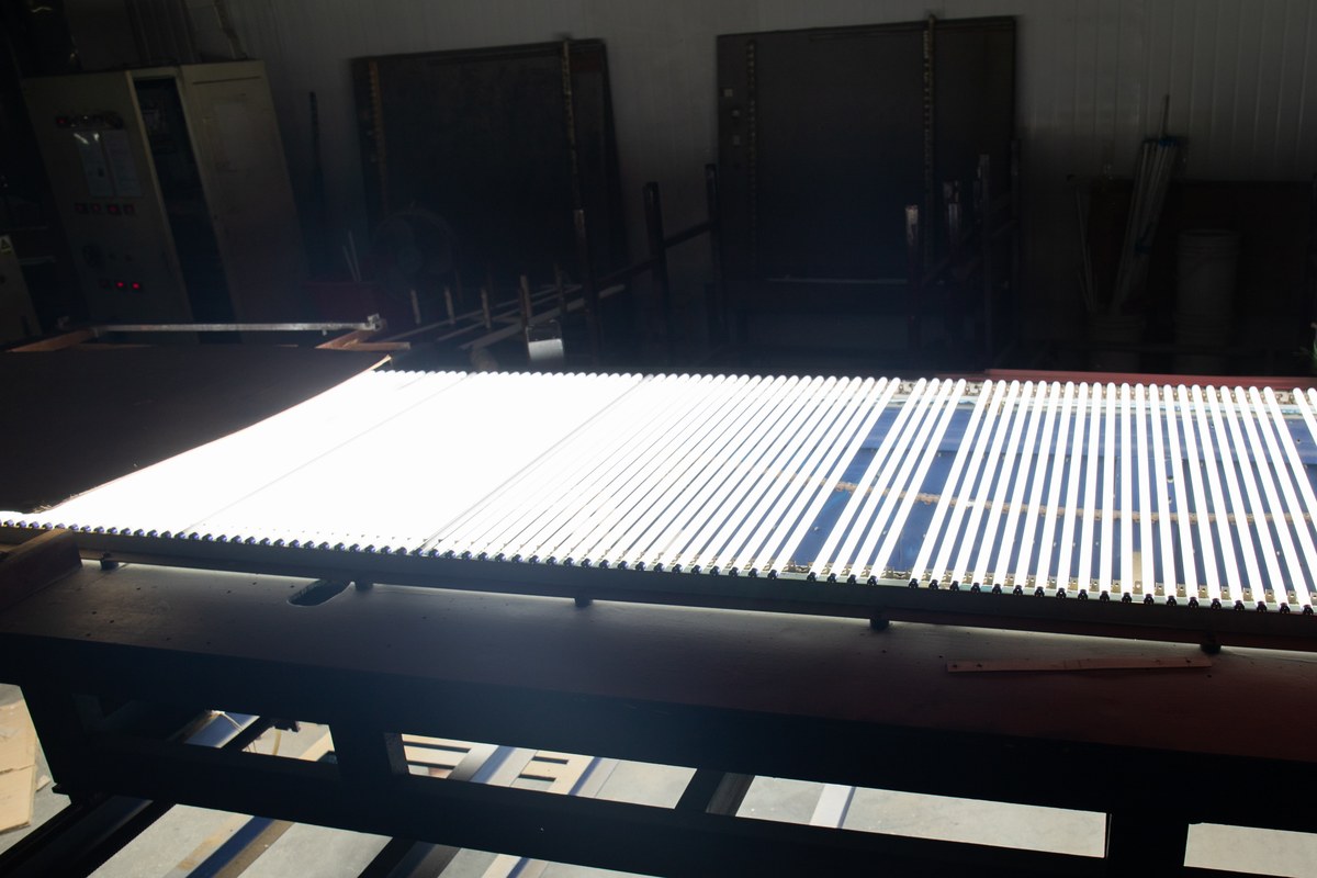
| Stress testing | Which failure modes are exercised and for how long? | An aging-room photograph alone |
| Production control | Is the approved design repeated by lot and revision? | One golden sample without BOM control |
| Field feedback | Are failures classified with a denominator and root cause? | Anecdotes without traceability |
Control Supplier and Version Changes
Driver behavior can change when a capacitor, controller IC, transformer, PCB, firmware or supplier changes. Freeze the approved BOM and revision, then define which substitutions require engineering review, re-test or customer approval.
Link the driver revision to the lamp model, production lot and test record. A replacement that matches nominal wattage can still change startup, output ripple, thermal behavior, protection or control compatibility. The LED tube supplier evaluation guide explains how to test sample-to-production consistency and change control.
Diagnose Symptoms Without Assuming the Driver Failed
No light, flicker, cycling, reduced output or control failure can involve the driver, but the same symptoms may come from the supply, ballast, sockets, wiring, LED board, temperature or control state. Capture the model, batch, architecture, input, fixture, operating history and symptom before replacing parts.
If multiple lamps on one circuit fail together, start with the shared supply and control boundary. If one lamp differs, compare its local connections and operating condition. Preserve failed parts and records for root-cause analysis. The LED light failure diagnosis guide provides a system-level sequence.
TLED Driver Qualification Checklist
Before release, confirm:
- The lamp architecture and market are defined.
- The LED-board current and voltage window is documented across relevant conditions.
- Input voltage, frequency, tolerances and disturbances are specified.
- Efficiency, PF, harmonics and inrush are measured separately.
- Thermal limits are verified in the complete tube and representative fixture.
- Fault protection and recovery behavior are recorded.
- Safety, isolation, wiring and installation evidence match the exact configuration.
- Flicker and output stability meet the application criteria.
- Dimming is validated as a complete driver-control-load system where required.
- Reliability, BOM, revision and supplier-change controls are auditable.
Use the lighting maintenance and spare-parts guide to carry the approved driver identity into service planning. For an OEM review, contact New Lights with the tube architecture, LED-board window, input market, fixture condition, controls and required evidence.
Frequently Asked Questions
Is wattage enough to select a TLED driver?
No. Wattage does not define the required current, LED-string voltage range, input behavior, thermal limits, protection, safety or control compatibility.
Is one forward-voltage value valid for every LED?
No. Forward voltage varies with package, current, temperature and production distribution. Use the exact LED-board operating range.
Does high power factor mean the driver is efficient?
No. Power factor and efficiency describe different relationships. Measure both under stated operating conditions.
Are electrolytic capacitors the only driver reliability concern?
No. Semiconductors, magnetics, resistors, solder joints, protection parts, thermal conditions and manufacturing variation can also limit performance or life.
Can any LED driver work with a dimmer carrying the same protocol label?
No. Verify the exact driver, controller, LED load, circuit quantity, settings and firmware as one system.
Can a driver be replaced by another model with the same wattage?
Only after confirming input, output, safety, thermal, protection, control, physical and approval compatibility. Nominal wattage alone is insufficient.
Editorial Sources
- U.S. Department of Energy, LED Luminaire Lifetime: Recommendations for Testing and Reporting: https://www1.eere.energy.gov/buildings/publications/pdfs/ssl/led_luminaire-lifetime-guide_june2011.pdf
- U.S. Department of Energy, LED Luminaire Lifetime Recommendations for Testing and Reporting: https://www.energy.gov/cmei/ssl/articles/led-luminaire-lifetime-recommendations-testing-and-reporting-0
- U.S. Department of Energy, LED Lighting and Controls Guidance for GSA: https://integratedlightingcampaign.energy.gov/sites/default/files/2024-10/LED%20and%20Controls%20Guidance%20for%20GSA_0.pdf