


A solar flood light should be sized as a complete off-grid energy system, not selected from LED wattage, panel wattage or battery amp-hours alone. Define the required lighting schedule first, calculate the nightly watt-hour load, size usable battery energy for the required autonomy, and then check whether the photovoltaic module can replace that energy during the weakest relevant solar period.
The key test is simple: can the exact system deliver the required light through the specified night and recover its energy reserve under the project’s realistic sunlight, temperature, shade and control conditions? If the inputs are not stated, a runtime claim cannot be compared reliably.
Separate Sizing From General Product Selection
This guide owns the calculation and runtime-validation task. For a broader review of mounting, environment, documentation and supplier evidence, use the outdoor solar lighting procurement guide. If the application itself is still undefined, the outdoor and solar lighting solution page provides the wider application context.
Sizing begins only after five inputs are fixed:
| Input | What must be stated | Why it changes the result |
|---|---|---|
| Lighting duty | Target area, mounting height, distribution, illuminance or task requirement | Determines the light output and electrical load actually needed |
| Operating profile | Full-output hours, dimmed hours, motion events, standby and dawn/dusk logic | Converts fixture power into nightly energy use |
| Design solar period | Coordinates, weakest relevant month, tilt, azimuth and shade | Determines the energy likely to be harvested |
| Storage objective | One-night operation, multi-night autonomy or managed load reduction | Determines usable battery energy and recovery time |
| Environment | Temperature, precipitation, dust, salt, wind and maintenance access | Changes battery availability, PV yield and installation requirements |
Do not begin with a catalogue runtime and work backwards. Begin with the lighting task and test whether the offered system closes the energy balance.
Calculate the Nightly Load in Watt-Hours
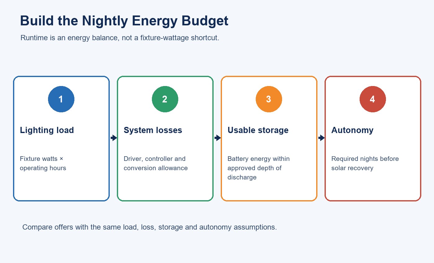
Power describes an instantaneous load; energy describes how much the system uses over time. For each operating mode, multiply input power by duration and add the results:
Nightly load (Wh) = Σ [mode power (W) × mode duration (h)] + control and standby energy
Use measured or model-specific input power where possible. Do not substitute a marketing wattage, LED-chip rating or nominal battery value. If the controller changes output during the night, each stage belongs on a separate line.
For motion-controlled systems, estimate both a normal and a demanding event profile. A doorway with ten brief activations and a busy loading area with near-continuous motion may use the same fixture but require very different storage.
Worked Example: Build the Load Before Selecting the Battery
Consider an illustrative project—not a New Lights model claim—with a 20 W flood light that must operate for four hours at full output and eight hours at 25% output. Assume the controller and sensor consume another 4 Wh per night.
| Operating segment | Input power | Duration | Energy |
|---|---|---|---|
| Full output | 20 W | 4 h | 80 Wh |
| 25% output | 5 W | 8 h | 40 Wh |
| Controller and sensor | — | — | 4 Wh |
| Total nightly load | 124 Wh |
This 124 Wh figure is the starting point, not the battery label. If motion events increase full-output time, recalculate the profile. If the required illuminance needs a different fixture input power, revise the load before touching the battery calculation.
The worked example also exposes a common procurement problem: two suppliers can both promise “all-night operation” while assuming different dimming schedules. Compare the actual watt-hour duty, not the phrase.
Convert Nominal Battery Energy Into Usable Energy
Nominal battery energy is approximately voltage multiplied by amp-hours, but the full nameplate value may not be available to the LED load. The usable amount depends on permitted depth of discharge, controller cutoff, discharge rate, temperature, aging allowance and conversion losses.
For an initial comparison:
Required nominal battery energy = required load energy ÷ combined usable fraction
Continue the example with an 80% permitted usable fraction, 90% discharge-path efficiency and an 85% temperature-and-aging factor:
124 Wh ÷ (0.80 × 0.90 × 0.85) ≈ 203 Wh nominal energy for one design night
If the project requires two nights of full specified duty without useful charging, the storage basis becomes approximately 406 Wh before any additional engineering margin. These factors are illustrative inputs. The real values must come from the exact battery, controller, operating temperature and project acceptance criteria.
Battery capacity cannot be judged from enclosure size. Request chemistry, cell configuration, nominal and usable energy, BMS functions, charge and discharge limits, cutoff thresholds, temperature behavior, cycle evidence and replacement provisions.
Size the PV Module for the Weakest Relevant Period
The U.S. Department of Energy distinguishes laboratory conversion efficiency from actual PV energy yield, which is affected by heat, dirt and shade. That distinction matters for a solar flood light: panel nameplate power is not the energy that reaches the battery.
An initial daily-energy estimate can be expressed as:
Daily PV energy (Wh) = module rating (W) × design-period peak-sun hours × system derating factor
If the example uses a 100 W module, 3.0 design-period peak-sun hours and a combined 70% derating factor, the estimated daily energy is:
100 W × 3.0 h × 0.70 = 210 Wh/day
Against the 124 Wh nightly load, that leaves 86 Wh for recovery and uncertainty on the assumed design day. It does not prove winter reliability. Shade, several weak days, charging limits or lower temperature-adjusted battery acceptance can remove the margin.
NREL’s PVWatts calculator is useful for solar-resource context, but NREL states that its predictions include assumptions and uncertainty. PVWatts models grid-connected PV and should not be treated as a direct runtime guarantee for a small off-grid light. Use location-specific resource data, then model the actual module, orientation, battery and controller.
Check Recovery After a Weak-Sun Event
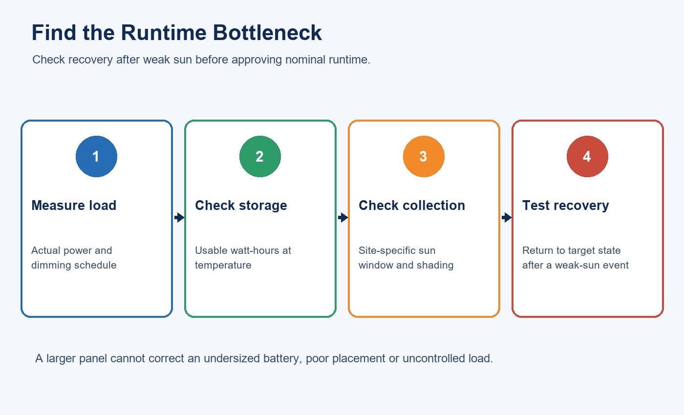
Autonomy and recovery are different questions. A large battery may run the light through two poor days, yet an undersized panel may take too long to restore the reserve while continuing to serve the nightly load.
Calculate the daily surplus after the normal load:
Recovery energy per day = estimated daily PV energy − nightly load
In the illustrative case, 210 Wh of estimated harvest minus 124 Wh of load leaves 86 Wh/day before further charging constraints. Replacing a 124 Wh deficit would therefore require more than one design day. If another weak-sun day follows, the system may never return to full reserve.
The second-order decision is therefore not merely “How many cloudy nights can the battery cover?” It is “How quickly can the complete system recover while still operating?” Record both autonomy and recovery targets in the RFQ.
Decide Which Constraint Becomes the Bottleneck
The first limiting factor changes by project:
| Project condition | Likely first constraint | Design response |
|---|---|---|
| Long winter nights | Nightly load and battery energy | Reduce duty intelligently or increase verified usable storage |
| Short winter charging window | PV collection and recovery margin | Improve exposure, orientation or module capacity |
| Partial daytime shade | Effective solar harvest | Relocate the panel or verify the shaded profile rather than using regional averages |
| Cold climate | Battery discharge and charging behavior | Use chemistry and controls suitable for the stated temperature range |
| Busy motion zone | Full-output event duration | Model demanding event frequency and sensor behavior |
| High mounting height or wide area | Optical distribution and required input power | Verify photometry before calculating energy |
This is why dividing battery watt-hours by fixture watts is incomplete. That shortcut ignores permitted discharge, losses, changing output modes, temperature and whether the panel can replenish the battery.
Verify Panel and Fixture Placement Separately
The best angle for collecting sunlight may not be the best angle for lighting the target or detecting motion. Check whether the panel, light heads and sensor can be aimed independently. Survey trees, buildings, roof edges, signs and expected vegetation growth during the design season.
The outdoor lighting installation checklist covers mounting, cable routing, aiming and commissioning issues that also apply to solar installations. For projects still comparing beam coverage and fixture geometry, review what an LED floodlight is designed to do before finalizing the electrical load.
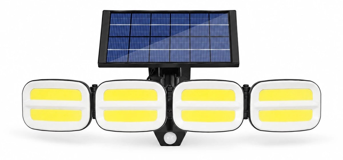
The published New Lights product page identifies this as one product family, not a universal sizing configuration. Use its model page to identify the exact configuration before applying product-specific values.
Define Control Behavior as Part of the Energy Model
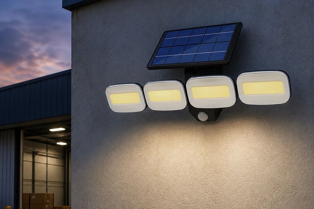
Controls can extend operation only by changing when or how brightly the light operates. Specify dusk threshold, time schedule, dimming stages, motion sensitivity, detection area, hold time, standby load, low-battery behavior and recovery logic.
Ask what the user sees as the battery approaches cutoff. Does the system dim gradually, skip a scheduled stage, shorten motion events or switch off? A long advertised runtime achieved through unreported dimming is not equivalent to a full-output requirement.
Test repeated motion events, false triggers from vegetation or traffic, and the transition near dawn. Use the demanding credible pattern in the calculation rather than a best-case demonstration.
Validate the Exact System and Record the Evidence
Model calculations narrow the design, but production-representative testing closes the decision. Test the complete combination of PV module, battery, controller, LED board, optics, sensor, enclosure and firmware. Record component revisions so a later substitution triggers an impact review.
Measure charging conditions, power in each mode, light output, dimming schedule, sensor response, battery state where available, temperatures and cutoff behavior. Add an outdoor trial at representative orientation and exposure. DOE’s storage evaluation guidance uses measured charge and discharge time-series data to assess deployed systems; the same evidence-first principle is useful here even though a solar flood light is much smaller than the systems covered by that method.
Commission the installed system by recording panel direction and tilt, shade, fixture aim, sensor field, mounting, seals and initial light levels. Monitor a period that includes weak-sun conditions. One successful night is not enough to establish seasonal performance.
For outdoor utility areas, the exterior utility area lighting guide helps connect energy sizing to access, glare, task visibility and maintenance priorities.
Put Comparable Inputs in the RFQ
| RFQ section | Information to provide or request |
|---|---|
| Site and task | Coordinates, area, mounting height, target distribution, required light level and operating schedule |
| Solar exposure | Design month, panel location, tilt, azimuth, shade survey and soiling assumptions |
| Load | Measured input power by mode, control consumption and demanding motion profile |
| Battery | Chemistry, nominal and usable Wh, cutoff, temperature factors, aging allowance and autonomy basis |
| PV and controller | Module rating, charging limits, conversion assumptions, protection and recovery calculation |
| Verification | Photometry, model-level documents, sample test, outdoor trial, production configuration and change control |
| Installation and service | Mounting, seals, access, cleaning, battery replacement, spare parts and recommissioning |
New Lights’ factory and manufacturing capabilities page describes the route for product sampling, documentation and production coordination. To review a specific project, contact New Lights with the location, required light, mounting plan, nightly schedule, autonomy target and proposed model.
Frequently Asked Questions
How many hours should a solar flood light run?
There is no universal correct runtime. Define the required full and dimmed output schedule, then verify it against usable battery energy, temperature, solar resource, losses and recovery time.
Can I size the battery by dividing watt-hours by fixture watts?
That gives only a theoretical duration. A defensible calculation also includes controller consumption, permitted depth of discharge, conversion losses, temperature, aging, cutoff behavior and changing output modes.
Does a larger solar panel guarantee reliable operation?
No. A larger module can increase potential harvest, but shade, orientation, temperature, controller limits, battery acceptance and the nightly load still control the result.
How many cloudy days of autonomy should I specify?
Choose autonomy from the service consequence, local weak-sun pattern, available installation space, maintenance plan and acceptable load reduction. Also calculate how quickly the system can recover after using that reserve.
Should annual-average sunlight be used for sizing?
Annual averages can hide the period when long nights and weak solar input occur together. Use the weakest relevant design period and document the chosen weather dataset, orientation, shade and losses.
Editorial Sources
- New Lights, “Solar Flood Light Premium FL Series”: https://new-lights.com/products/solar-lighting/solar-flood-lights/solar-flood-light-premium-fl-series/
- New Lights, “Outdoor Solar Lighting Procurement Guide for Buyers”: https://new-lights.com/blog/outdoor-solar-lighting-procurement-guide/
- U.S. Department of Energy, “Photovoltaic System Design and Energy Yield”: https://www.energy.gov/cmei/systems/photovoltaic-system-design-and-energy-yield
- National Renewable Energy Laboratory, “PVWatts Calculator”: https://pvwatts.nrel.gov/
- U.S. Department of Energy, “Battery Energy Storage System Evaluation Method”: https://www.energy.gov/cmei/femp/articles/battery-energy-storage-system-evaluation-method












