Exterior utility-area lighting should be planned around the service task, access route and occupied working position—not around an empty nighttime image or a single target wattage.
Map how people approach the area, what they need to read or operate, which doors and vehicles can block light, and how the system must behave during normal operation, maintenance and control failure. This task-first method applies to service yards, plant rooms with exterior access, loading interfaces, meter and valve areas, refuse points and other back-of-house outdoor spaces.
Define the Task Boundary and Service Geometry
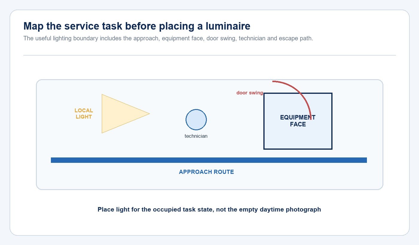
Start with a marked plan and site photographs. Identify approach routes, steps, curbs, gates, equipment faces, labels, disconnects, valves, door swings, ladders, waste or loading interfaces, vehicle paths and the position in which a technician must stand. Record whether work is routine, occasional, emergency-only or dependent on portable tools.
The boundary is wider than the equipment itself. A light can illuminate a wall while leaving the approach dark, create a sharp shadow across a label, or sit where an open door blocks the beam. Utility areas form one part of the broader Outdoor, Garden & Solar Lighting solution, but their priority is reliable access and task visibility rather than decorative composition.
Separate Route, Area and Local Task Lighting
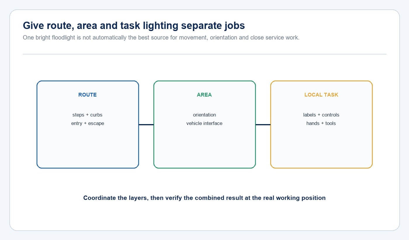
Route lighting supports movement to and from the service zone. Area lighting provides general orientation and helps reveal vehicles, stored items and boundaries. Local task lighting serves labels, controls, connection points and the hand-tool area. Treating these as separate jobs prevents one high-output floodlight from being asked to solve incompatible beam and mounting requirements.
The layers can share equipment, but their acceptance criteria differ. Route light should reveal changes in level and obstructions without creating disabling glare. Area light should provide usable coverage across the active zone. Local light should reach the equipment face from a direction that remains useful when a person is standing at the task.
Test Shadows, Doors and Vehicle Obstructions
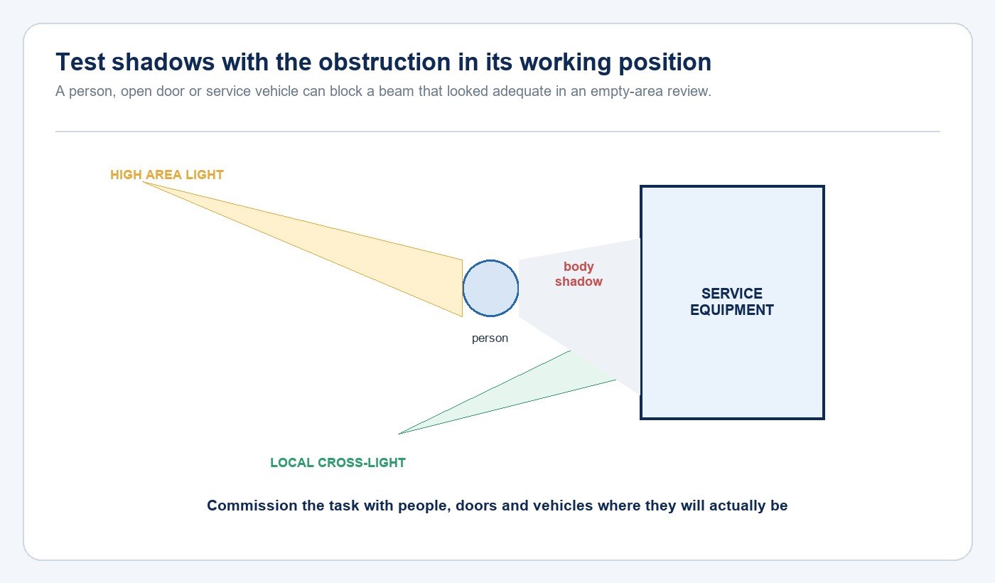
Review the beam with the site in its working state. Position a person at the equipment, open the enclosure door through its full operating arc, and place a representative vehicle or bin where it normally sits. Check whether the technician’s body, the door or the temporary obstruction removes light from the point that needs to be seen.
A local cross-light can be more effective than simply increasing output from a high mounting point. The useful answer depends on equipment orientation, glare risk, mounting access and nearby boundaries. Record the difficult state in the brief so it is not lost when the supplier sees only a clean plan.
Select Distribution, Mounting and Environmental Evidence
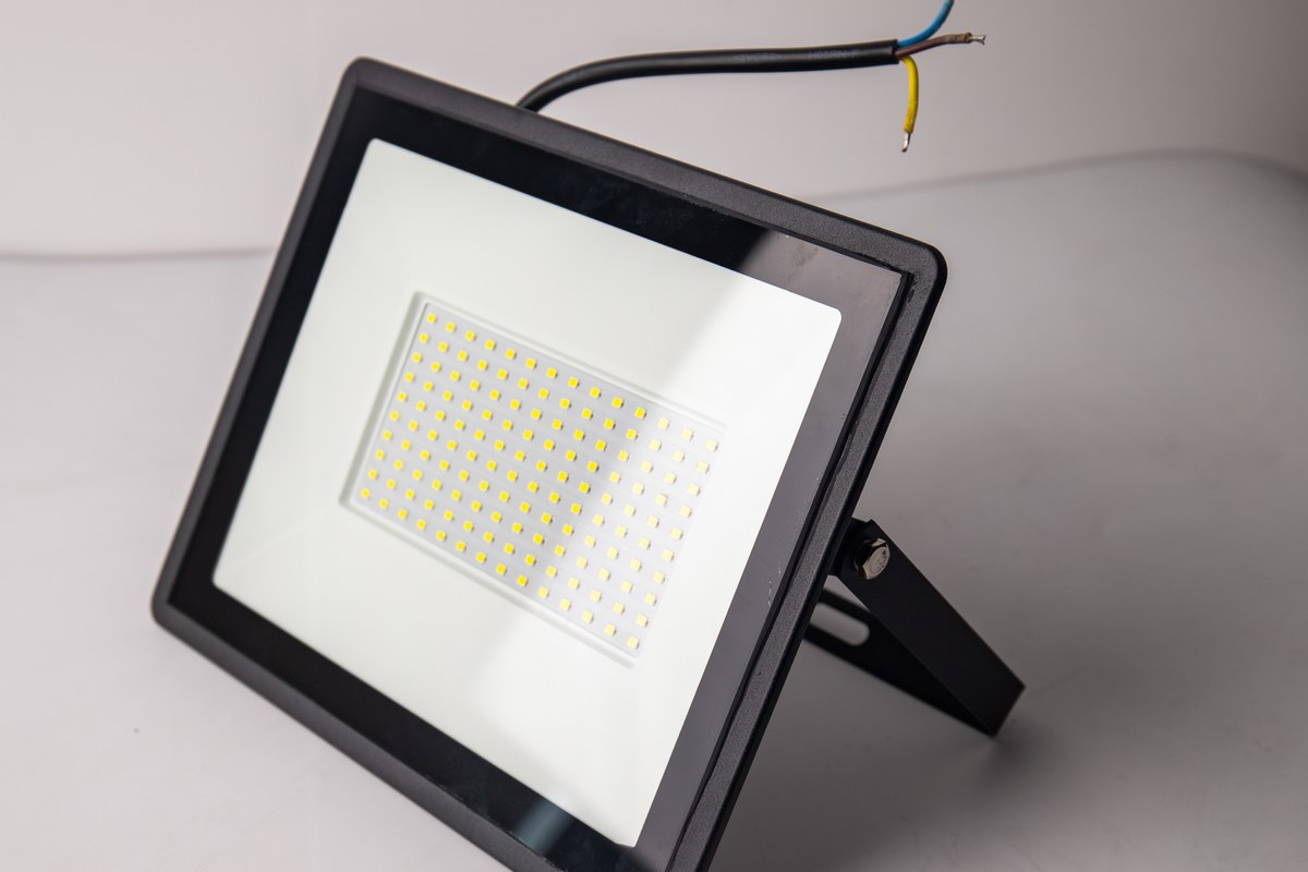
Choose the distribution and aiming range from the mapped task. Wide distribution can support an open yard; controlled floodlighting can serve a façade or equipment zone; a local wall-mounted source can reduce task shadows. Compare the exact product’s photometric file, mounting range, aiming retention, cable entry, enclosure construction, control interface and maintenance method.
Match the product evidence to rain, wind, dust, corrosion, washdown, impact and temperature conditions. An IP code addresses defined ingress tests, not every environmental risk; use the IP ratings for LED lighting guide to separate ingress scope from corrosion, impact and installation quality. For United States facilities, OSHA also requires outdoor electrical equipment to be suitably enclosed and protected from unauthorized contact, vehicle traffic and accidental spillage or leakage.
| Design question | Evidence to request | Field check |
|---|---|---|
| Where must light reach? | Photometric file and aiming limits | Equipment face and occupied task position |
| Will the aim stay fixed? | Bracket, fastener and locking method | Vibration, wind and maintenance access |
| How is the cable sealed? | Entry detail and installation instruction | Orientation, gland and drip path |
| What exposure applies? | Ingress, material and temperature evidence | Rain, dust, corrosion, impact and washdown |
| How will it be serviced? | Access and replacement method | Reach, isolation and obstruction clearance |
Define Controls and Failure States
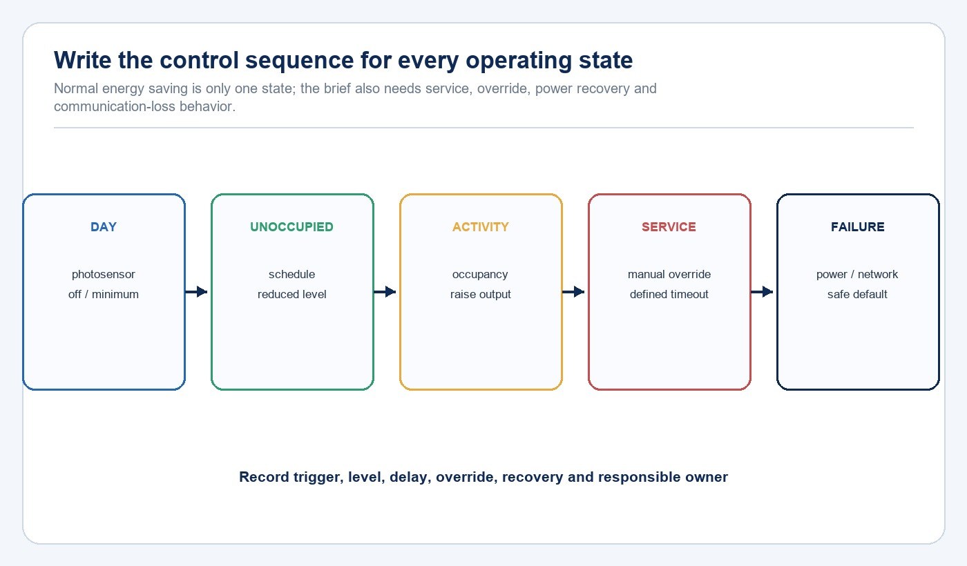
Write a sequence of operation instead of listing sensor names. Define the daylight state, scheduled unoccupied state, response to activity, manual service override, timeout, restoration after power loss, and the result of a communication or sensor failure. If a critical access function must remain available independently of a networked scene, state that requirement explicitly.
U.S. Department of Energy exterior-lighting guidance discusses schedules, photosensors and occupancy strategies and calls for commissioning of sensor placement, sensitivity, timeout and programmed behavior. The control narrative should also identify who can change settings and how the accepted values will be handed over.
Commission the Real Service Task
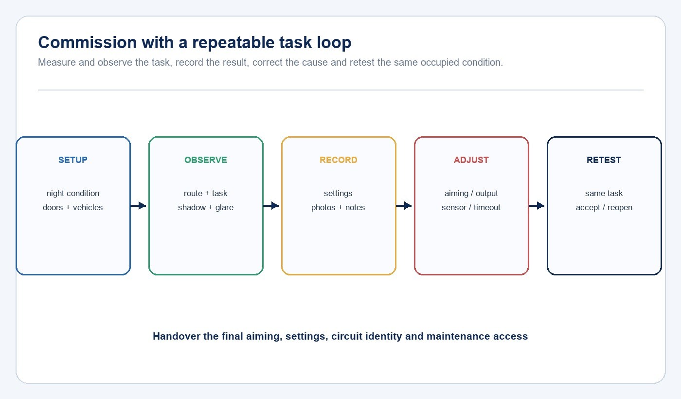
Commission after dark with representative people, doors, vehicles and control states. Walk the approach route, read the required labels, operate the equipment where permitted, and observe shadows, glare, spill and dark adaptation. Measurements can support the record, but the test points and instrument conditions must correspond to the task rather than a convenient empty location.
Record luminaire identity, aiming, control settings, circuit or node, test condition, photographs and unresolved exceptions. If the result is poor, correct the cause—distribution, position, obstruction, output or control behavior—and repeat the same task. The U.S. Department of Energy guidance also calls for functional testing and delivery of as-built locations, control information and operation and maintenance material.
| Commissioning state | What to observe | Record |
|---|---|---|
| Approach | Route continuity, obstacles and glare | Direction, setting and exception |
| Equipment task | Labels, controls, hands and body shadow | Occupied position and door state |
| Vehicle or bin present | Blocked beam and remaining access | Representative obstruction position |
| Sensor transition | Detection, delay and timeout | Trigger location and accepted values |
| Power/network recovery | Default level and restoration | Recovery time and manual action |
Exterior Utility Area Lighting Checklist
- Map approach routes, level changes, gates and escape paths.
- Mark equipment faces, labels, disconnects, valves and working positions.
- Show door swings, vehicles, bins and other likely beam obstructions.
- Separate route, area and local task-lighting roles.
- Compare photometric, mounting, aiming and cable-entry evidence.
- Match ingress, material, temperature and impact evidence to the exposure.
- Write daylight, vacancy, activity, override and failure states.
- Commission the occupied task at night and record accepted settings.
- Hand over luminaire identity, controls, maintenance access and exceptions.
Remote sites that cannot support a fixed power route need a separate energy and autonomy review; use the outdoor solar lighting procurement guide for that decision. Product files can be reviewed through the New Lights download center, while the New Lights factory and manufacturing overview provides the production context behind project coordination.
Frequently Asked Questions
Can one floodlight cover an entire utility area?
It may provide general area light, but a technician, door or vehicle can still shadow the equipment face. Verify route, area and local task roles separately.
Should exterior utility lights use motion sensors?
Occupancy response can reduce output during inactivity, but the brief must define detection coverage, delay, timeout, override and the safe result of a sensor or communication failure.
Does an IP65 rating prove suitability for every outdoor utility area?
No. It addresses defined dust and water ingress tests. Corrosion, impact, cable entry, mounting orientation, temperature and maintenance exposure still require separate evidence.
What should be included in handover?
Record luminaire and circuit identity, final aiming, control settings, sensor locations, test conditions, photographs, maintenance access and unresolved exceptions.
Prepare the Project Brief
Send the marked site plan, nighttime photographs, service tasks, obstruction states, operating schedule, exposure, mounting constraints, control narrative and available product documents through the New Lights project enquiry form.
Editorial Sources
- U.S. Department of Energy Better Buildings — Exterior Lighting Controls Guidance: https://betterbuildingssolutioncenter.energy.gov/resources/exterior-lighting-controls-guidance
- U.S. Department of Energy FEMP — Purchasing Energy-Efficient Exterior Lighting: https://www.energy.gov/cmei/femp/purchasing-energy-efficient-exterior-lighting
- U.S. Occupational Safety and Health Administration — Subpart S, Electrical: https://www.osha.gov/etools/subpart-s