


A rotatable LED linear fixture should be specified as an aiming system, not by rotation range alone. Define what rotates, the usable angle, operating and holding torque, allowable backlash, wiring path, mounting orientation and target beam position. Then test angle retention and light distribution before and after repeated adjustment.
The range answers only “How far can it move?” It does not answer whether the fixture stays where it is aimed, feels consistent across lengths, protects internal conductors or returns the beam to the same target. Those are separate acceptance decisions.
Start With the Lighting Task and Mounting Geometry
Identify the surface that needs light: a worktop, shelf, display, wall or circulation route. Record the mounting height, setback, obstruction, observer position and target aiming direction. The useful range is the range that reaches the task without colliding with the wall, cable, connector or mounting surface.
For under-cabinet work, the under-cabinet light bars versus linear fixtures guide helps define concealment, continuity and wiring before the rotation mechanism is selected. If the product is part of a connected run, also establish feed position and service access.
| Requirement | What to define | Acceptance evidence |
|---|---|---|
| Target surface | Dimensions, viewing direction and required beam placement | Aiming drawing and installed sample |
| Mounting | Wall, ceiling, shelf or cabinet orientation | Exact bracket and fixing detail |
| Usable angle | Zero reference, positive and negative direction, working range | Dimensioned drawing and angle check |
| Clearance | Cable, connector, switch and nearby surfaces | Rotation sweep inspection |
| Adjustment frequency | One-time commissioning, seasonal or frequent use | Cycle profile tied to the application |
An oversized range can create unnecessary cable movement or collision risk. Select the smallest controlled range that covers the actual aiming task.
Clarify Which Component Rotates
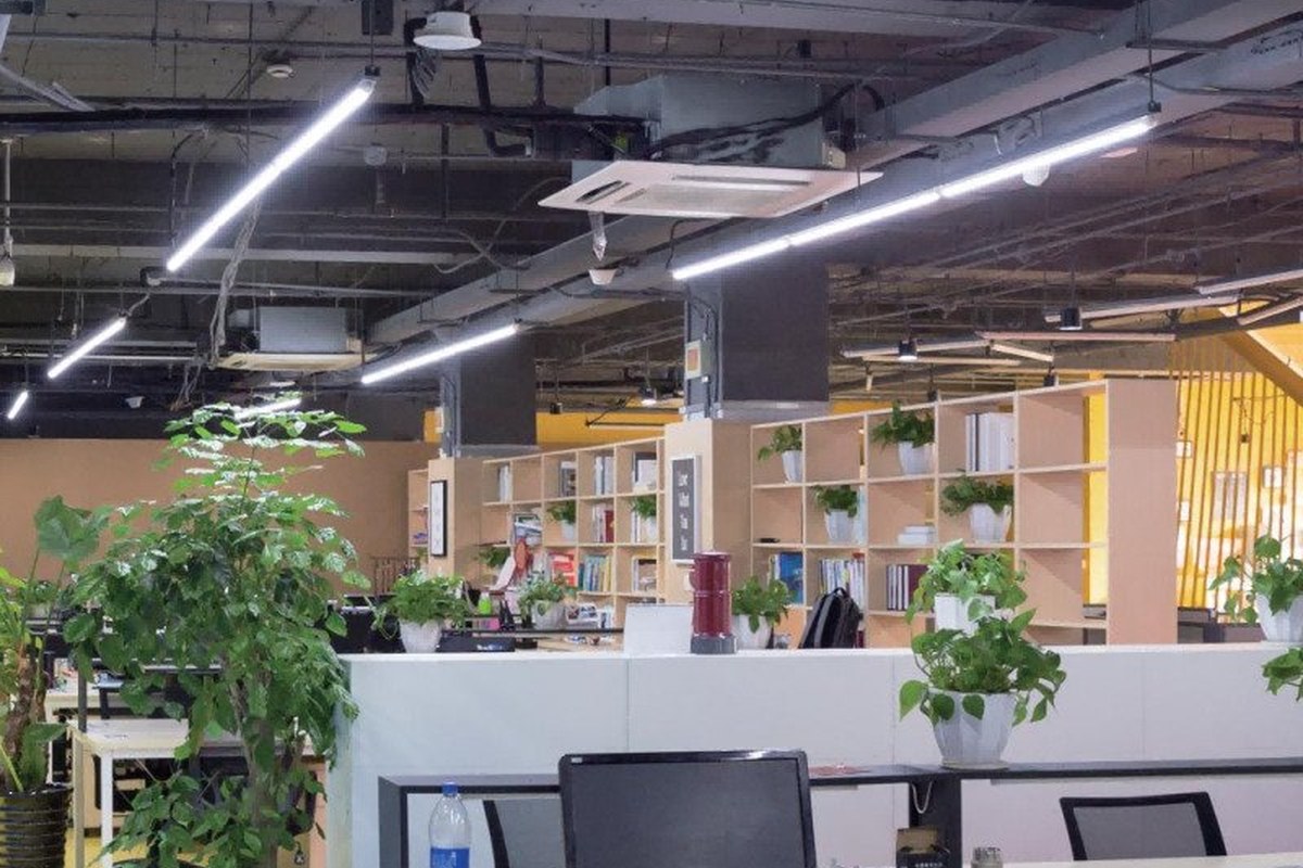
Determine whether the complete luminaire body rotates, only the optical bar moves, or a separate bracket changes the mounting angle. Identify the fixed housing, pivot axis, end supports, stops, connectors and surfaces touched by the installer.
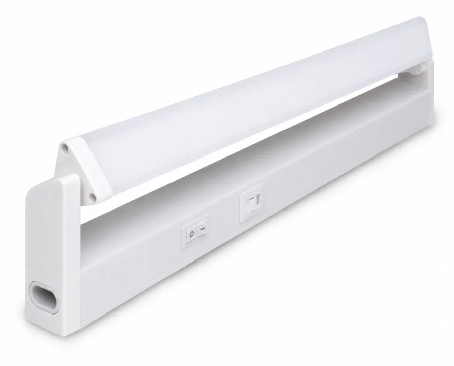
The current New Lights product page identifies the Surface-Mounted Rotatable LED Linear Fixture as a fixed full-plastic housing with a light bar that rotates through up to 170 degrees. Its five published lengths run from 297 to 1434 mm. Treat the stated range as a family feature; confirm the exact model, reference angle and installation clearance in the sample drawing.
Do not combine a bracket fixing angle with the optical bar’s rotation range. The zero position should be visible on the drawing, and the permitted sweep should show where movement stops in each direction.
Choose the Holding Principle Deliberately
Rotation can be held by friction, detents, toothed interfaces, springs, fasteners or a combination. Each method creates a different adjustment feel and wear pattern.
A friction joint offers continuous aiming, but it needs enough resistance to hold position against fixture weight, cable force and incidental contact. A detent joint offers repeatable positions, but the position spacing must match the application and the teeth must tolerate repeated engagement. A screw-clamped joint can hold firmly but may require tools and can be over-tightened.
| Holding method | Main advantage | Main risk to verify | Best fit |
|---|---|---|---|
| Friction pivot | Continuous angle selection | Torque drift, wear and length-dependent sag | Fine commissioning adjustment |
| Detent | Repeatable defined positions | Backlash, tooth wear and audible clicks | Repeated preset aiming |
| Clamped fastener | High holding force | Tool access and assembly variation | Infrequent adjustment |
| Spring-assisted joint | Controlled feel over a range | Fatigue and temperature sensitivity | Heavier moving sections |
The exterior appearance may not reveal the internal holding method. Ask for the section drawing, material callouts, tolerance stack and assembly controls that influence the pivot.
Specify Operating Torque and Holding Torque Separately
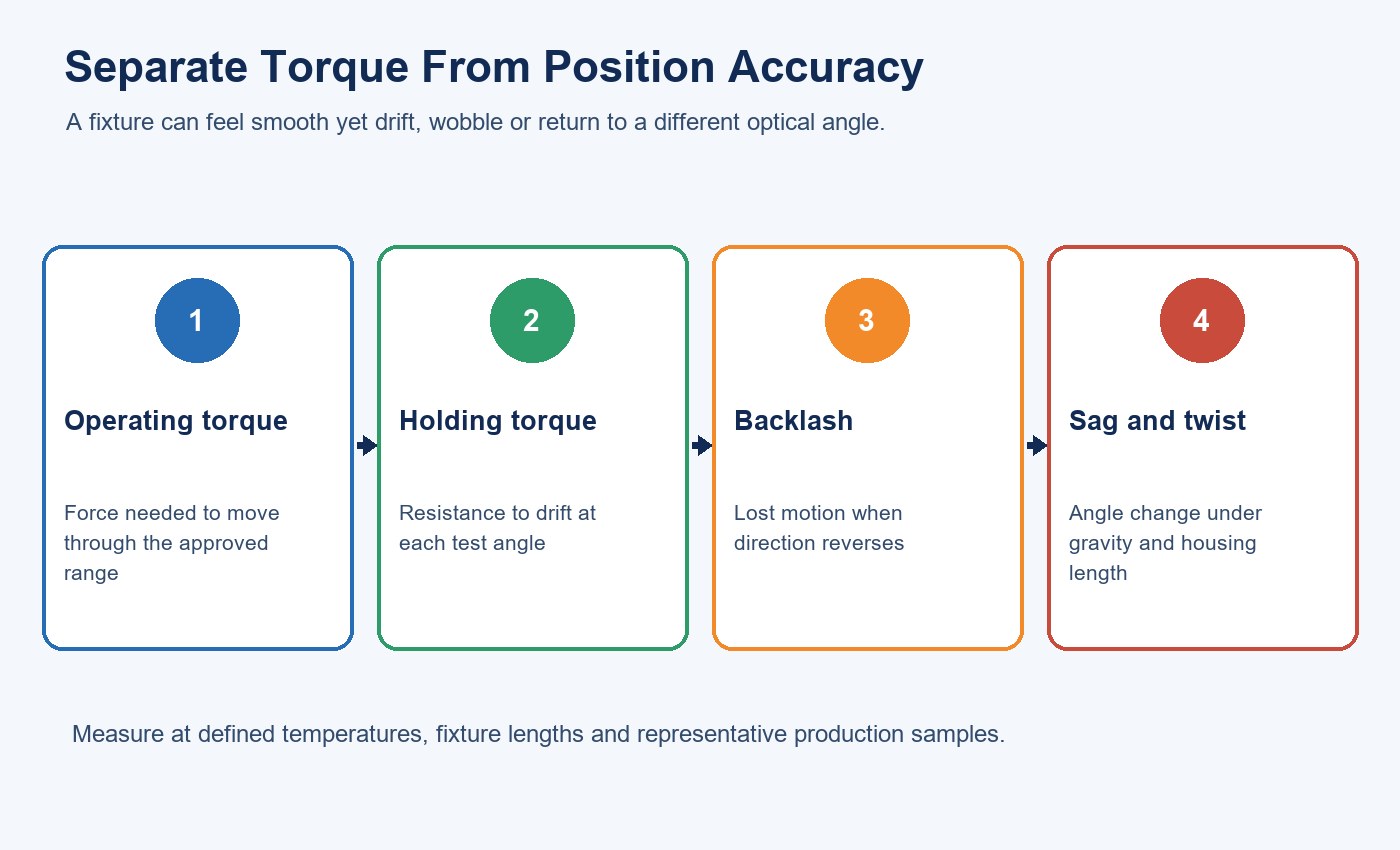
Operating torque is the torque required to start and continue movement. Holding torque is the resistance to unintended movement after positioning. Both need a minimum and maximum window.
If operating torque is too low, the bar may feel loose or move during cleaning. If it is too high, the installer may overload the mount, twist the housing or apply force through the diffuser. Holding torque must be checked at several angles because gravity and cable forces change with orientation.
Measure breakaway torque and running torque in both directions at a controlled adjustment rate. Record room-temperature results first, then repeat at the relevant low and high operating conditions after stabilization. Compare the shortest and longest model because mass distribution and housing stiffness change with length.
Example Mechanical Acceptance Matrix
The numerical limits should come from the application and product design, but the matrix structure can be fixed before samples arrive:
| Test | Initial sample | After thermal conditioning | After cycling |
|---|---|---|---|
| Breakaway torque | Record clockwise and counterclockwise | Remains inside approved window | Change remains within approved tolerance |
| Running torque | Smooth through usable range | No binding at temperature limits | No abrupt low-resistance zones |
| Holding torque | Holds each target angle | No temperature-driven drift | Retains the specified minimum |
| Backlash | Measure at optical axis | No material increase | Remains within angular limit |
| Housing alignment | Compare both ends | No distortion or interference | No twist that changes beam aim |
This turns words such as “stable” and “precise” into measurements that purchasing, engineering and quality teams can review together.
Control Backlash, Wobble, Sag and Twist
Backlash is angular movement at the control point before the optical section meaningfully changes position. Wobble can originate from pivot clearance, flexible supports, housing distortion or uneven assembly.
Set the fixture at defined angles and approach each target from both directions. Measure the final optical-axis angle rather than only the position of an end cap. Check wall, ceiling and inverted orientations when they are part of the intended use.
Long fixtures need measurements at both ends. If the housing twists, one end can aim differently from the other even while the center appears correct. Record immediate sag after release and any change after a defined dwell period.
Protect Wiring and Connectors Through the Full Sweep
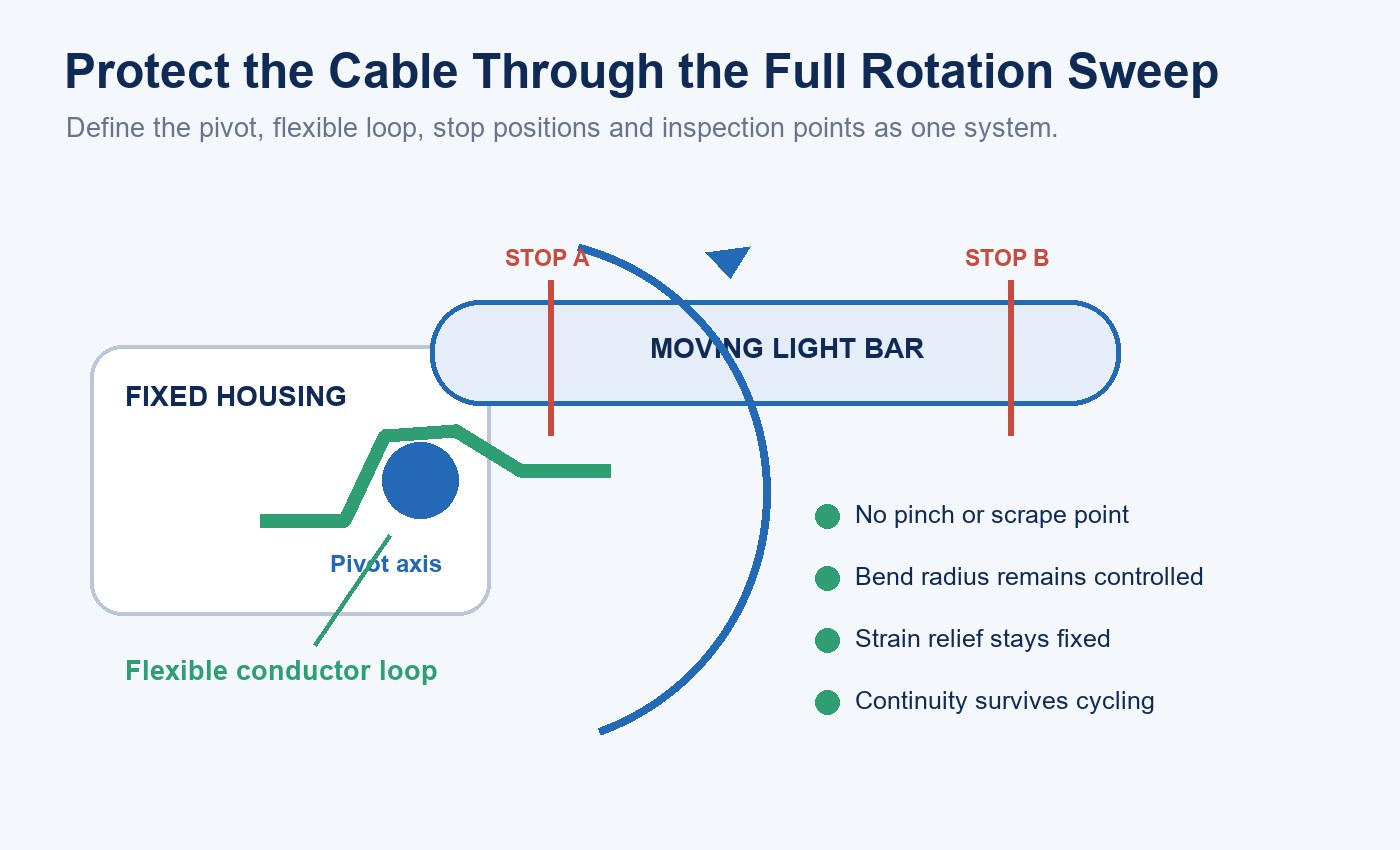
The moving section must not pinch, scrape or repeatedly bend conductors at one sharp point. Review conductor length, routing, bend radius, insulation, strain relief and contact with moving parts. Physical stops should keep the user away from a position that overstresses the wiring.
Cycle the mechanism while monitoring electrical continuity. After the cycle test, inspect conductors, strain relief, connectors and insulation near the pivot. For interconnectable products, confirm that link cables and end connectors remain clear in every permitted angle.
Switches and local controls should remain accessible after aiming. A fixture that reaches the target angle but traps the cable or hides the switch has not met the installation requirement.
Check Materials, Temperature and Assembly Variation
Plastic pivots can change friction with molding variation, surface wear and sustained load. Metal fasteners, bushings and housings expand at different rates. Lubricants, if used, add their own temperature and aging behavior.
Test the mechanism after the complete fixture reaches its normal thermal condition. Include the installation orientations and environmental range stated in the project. Observe clearance, binding, torque change, creep and visible wear.
Assembly controls matter as much as material choice. Fastener torque, molded-part dimensions, pivot insertion force and end-support alignment can change the feel between units. Record a distribution across samples rather than relying on one “good” unit.
Define Quiet Adjustment Without Promising Silence
Some mechanisms intentionally click because they use detents. Others may squeak, scrape or snap because surfaces interfere. Decide whether the project needs quiet adjustment, quiet operation after aiming or both.
If adjustment noise matters, define the mounting surface, background level, microphone distance, movement rate and event to be measured. Separate pivot noise from driver buzz, loose-part vibration and structure-borne sound during operation.
The practical acceptance criterion may be “no scraping, squeaking or impact event audible at the stated distance under the test background” rather than an absolute claim of silence. If a numerical sound limit is required, align the test method and instrument before samples are compared.
Run a Cycle Test That Represents Real Use
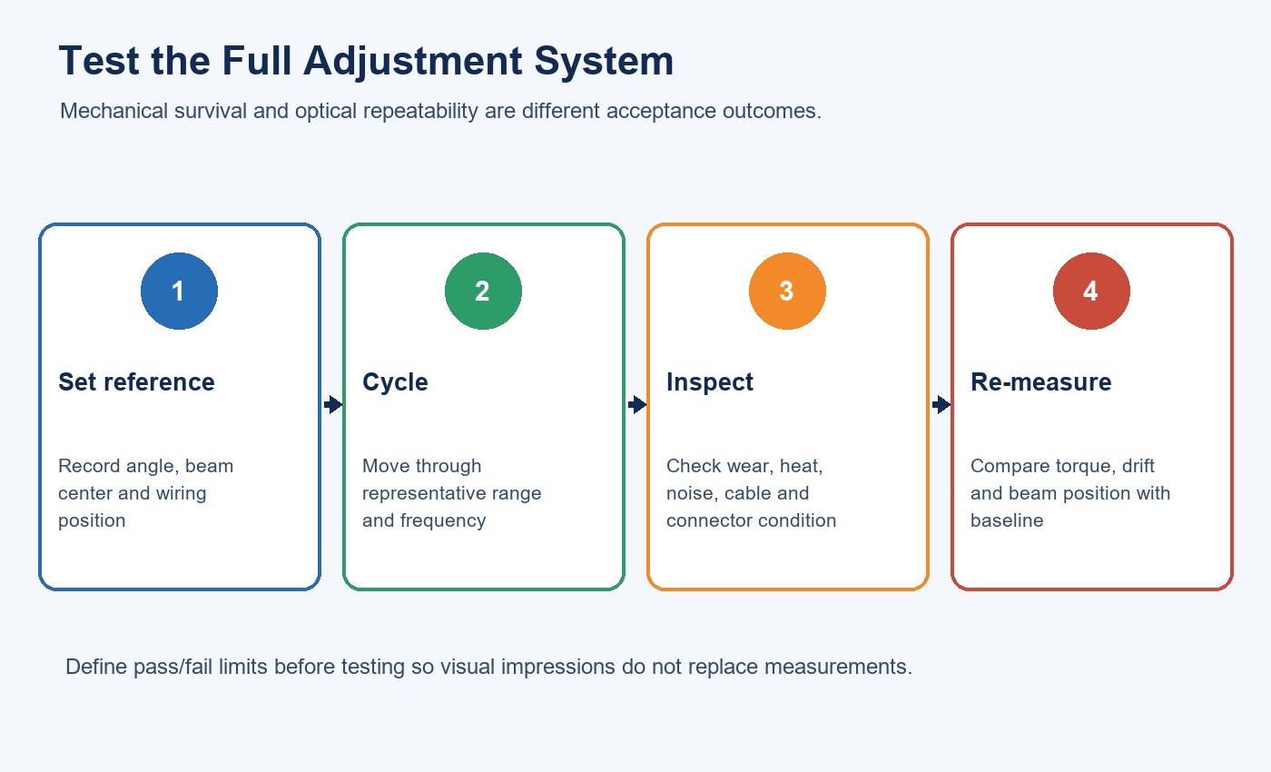
Create a cycle profile from the application. A fixture adjusted once during commissioning does not need the same cycle as a retail display changed every week. Define start and end angles, speed, dwell, mounting orientation, electrical state, temperature and number of cycles.
At planned intervals, record torque, backlash, angle retention, noise and visible wear. Inspect pivots, stops, supports, fasteners, housing, wiring and connectors. After the final interval, repeat electrical safety, thermal and functional checks.
| Checkpoint | Mechanical checks | Lighting and electrical checks |
|---|---|---|
| Before cycling | Range, torque, backlash, alignment and appearance | Input, function, beam reference and control access |
| Intermediate intervals | Torque trend, debris, looseness and stop condition | Continuity, flicker symptoms and beam shift |
| Final interval | Holding torque, sag, twist and damaged parts | Electrical safety, temperature and photometric repeatability |
| Dwell after cycling | Angle retention under load | Stable operation at the retained angle |
Trend data is more useful than a single final pass. It reveals whether the joint is gradually loosening, tightening or developing inconsistent positions.
Verify Optical Repeatability, Not Just Mechanical Motion
The purpose of rotation is to aim light. Mark several target angles and measure the beam center or illuminance pattern after repeated approaches from both directions. Record the target position, distribution, uniformity and any difference between fixture ends.
Rotation should not unseat the diffuser, create gaps or introduce a bright line near the pivot. If the product includes CCT or output switches, confirm that movement does not disturb those controls or their wiring.
For a broader explanation of how beam spread translates into a workplane pattern, use the T8 integrated fixture beam-angle guide. The rotatable-fixture test adds angle retention and return-to-position performance to that optical task.
Use the Surface-Mounted Rotatable LED Linear Fixture page to identify the exact length and published configuration before setting the test matrix.
Sample Production Variation and Control Changes
Prototype performance does not represent the full production distribution. Include samples from relevant lengths, production periods, material lots, molds or cavities and assembly operators according to project risk.
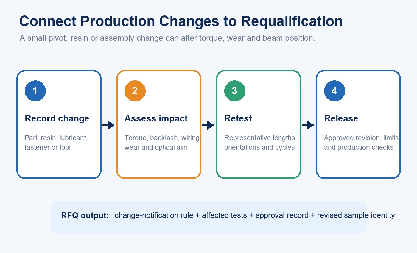
Set incoming or end-of-line checks for angle range, stops, operating feel, holding torque, backlash, alignment, appearance and function. Control changes to pivot parts, plastic resin, lubricant, fasteners, wiring and assembly tools because small changes can alter friction or long-term retention.
The LED lighting sample evaluation checklist helps connect the mechanism test to exact product identity, deviations and production release. For manufacturing review, New Lights’ factory and manufacturing capabilities page describes sampling and coordination routes.
Put the Mechanism Requirements in the RFQ
Provide the mounting orientation, fixture length, target surface, usable aiming range, adjustment frequency, environmental range, cable arrangement and acceptance windows. Ask the supplier to identify the holding method, materials, stops, torque controls and available test evidence.
Request a dimensioned drawing and production-representative samples. Record the approved model revision and define which changes require requalification. To discuss a specific project, contact New Lights with the installation drawing, fixture length, aiming positions and mechanical acceptance matrix.
Frequently Asked Questions
Is a larger rotation range always better?
No. The useful range should reach the target while protecting wiring, connectors, switches, mounting clearances and physical stops.
What is the difference between operating and holding torque?
Operating torque moves the fixture. Holding torque resists unintended movement after it is positioned. A practical specification needs acceptable windows for both.
How should angle drift be tested?
Set defined angles in each mounting orientation, measure the optical-axis position after release and repeat after dwell, temperature exposure and cycling.
Why should different fixture lengths be tested?
Mass distribution, leverage, housing stiffness and twist change with length. A short sample may not represent the longest model.
Can a rotatable fixture be described as silent?
Use a defined acoustic requirement instead. Intentional detent clicks, mechanical squeaks, driver noise and structure-borne vibration have different causes and test methods.
Editorial Sources
- New Lights, “Surface-Mounted Rotatable LED Linear Fixture”: https://new-lights.com/products/led-linear-fixtures/linear-battens/rotatable-led-linear-fixture/
- New Lights legacy site, “Rotatable Linear Fixture”: https://www.new-lights.com/product/led-linear-fixtures/rotatable-linear-fixure.html
- New Lights, “LED Linear Fixtures” catalogue: https://new-lights.com/new-lights/2024/12/06/ledlinearfixtures.pdf












