An ultra-slim LED panel should not be selected by body thickness alone. First identify whether the panel is backlit, edge-lit or frame-style. Then check the exact drawing, total ceiling clearance, photometry, glare calculation, driver, flicker, thermal conditions and mounting method for the ordered configuration.
This distinction matters because a thin body can still require separate space for a driver, connectors, cable bends, controls or an emergency module. It can also fit the opening but fail the project because the distribution, surface appearance, dimming behaviour or service access is wrong.
Identify the Panel Architecture First
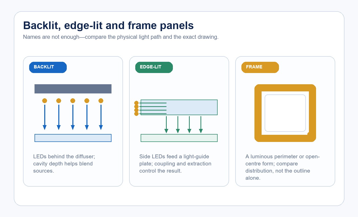
In a backlit panel, LEDs are arranged behind the luminous surface and direct light toward the diffuser. The cavity between the LED board and diffuser helps blend individual sources. Reducing that distance changes the optical problem: LED pitch, diffuser transmission and mixing depth must still prevent visible bright spots.
An edge-lit panel places LEDs along one or more edges of a light-guide plate. Optical patterns redirect light toward the front. This arrangement can support a very thin body, but the result depends on edge coupling, light-guide material, extraction pattern and the thermal path from the side-mounted LEDs.
A frame panel produces light around a perimeter or uses an open-centre visual form. It may be thin, but it should not be treated as a full-luminous-area panel without comparing its distribution and room effect.
For a component-level introduction, read what an LED panel light is. The architecture is the starting point; it does not by itself settle glare, flicker, lifetime or installation suitability.
Read Thickness From the Exact Drawing
Thickness figures must stay attached to a specific model and drawing. The New Lights slim/backlit comparison page, for example, pairs several SE and BE references with 9 mm and 30 mm body heights. Those figures demonstrate that products presented together can still have different architectures and physical depths; they are not a universal rule for all edge-lit or backlit panels.
The current Tunable White Backlit LED Panel is a product-family starting point. For an order, freeze the purchase reference, drawing revision, outside dimensions, body height, connector projection, driver and mounting kit. The signed configuration—not the category name—controls what is being reviewed.
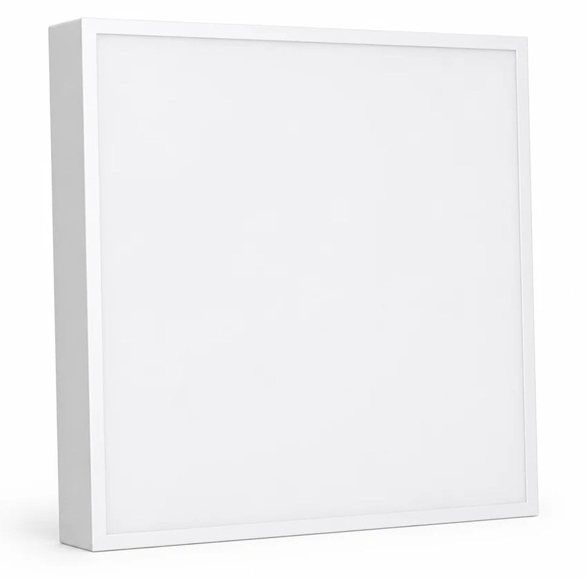
If several nominal sizes are being compared, use the LED panel size planning guide to separate grid module, outside dimension, opening and layout requirements.
Calculate Total Installation Depth
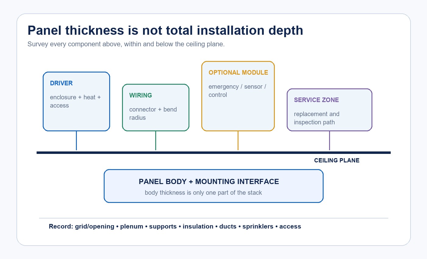
Panel body height is only one part of the installation stack. A separate driver needs room for its enclosure, connectors, cable bend radius, ventilation and future access. Sensors, control interfaces and emergency equipment can add more components above the ceiling plane.
Survey the grid or opening, plenum, insulation, ducts, sprinklers, support points and access route. Record whether the driver can be reached without removing unrelated building elements. For surface and suspended arrangements, include the approved frame, suspension set, canopy and fixing geometry.
The LED panel installation guide compares recessed, surface, suspended and ceiling-mounted methods. Qualified personnel should still follow the exact product instructions and local project requirements.
Evaluate the Optical Result, Not Just the Luminous Surface
A panel can look even when viewed directly yet deliver the wrong distribution at the task. The reverse is also possible: acceptable horizontal illuminance can coexist with distracting bright areas, reflected images on screens or weak vertical illumination.
Use the exact model photometric file in the project layout, then evaluate a representative sample in the intended room. When appearance matters, inspect the luminous surface at full output and relevant dimming levels. Compare centre-to-edge variation, seams, LED images, diffuser texture and color consistency.
| Decision question | Evidence to request | What to check in the pilot |
|---|---|---|
| Will the layout reach the task target? | Exact-model photometric file and lumen data | Measured horizontal and vertical illuminance |
| Will the panel look uniform? | Luminance image or defined surface-uniformity method | Hot spots, dark edges, seams and dimmed appearance |
| Will glare be controlled? | UGR table or calculation inputs plus photometry | High-angle brightness and screen reflections from real positions |
| Will color remain consistent? | Ordered CCT, CRI and color-tolerance record | Adjacent panels, finishes and dimmed states |
Do not replace this review with a bare-lumen or efficacy comparison. Optics, mounting height, spacing, room surfaces and viewing direction all affect the usable result.
Apply UGR to the Room, Not to a Headline
Unified Glare Rating is used to evaluate discomfort glare in indoor lighting installations. Material from the International Commission on Illumination (CIE) shows that the calculation depends on source luminance, source size and position, observer direction and background luminance. A product-page phrase such as “UGR below 19” therefore needs the exact photometric basis and the project conditions in which it is applied.
Ask which model and luminous surface the table represents, which spacing-to-height ratios were used and whether the source has strongly non-uniform luminance. Run the room calculation with the actual layout. Then inspect the likely occupant positions, including screens and glossy work surfaces, because a calculation does not show every reflection or local brightness pattern.
Test Flicker and Dimming as One System
Flicker performance is not established by the panel body or a “dimmable” checkbox. The US Department of Energy explains that the light waveform can change with driver loading, dimming level and the waveform supplied by the dimmer. That is why the exact driver, control and operating state must travel with the test result.
Freeze the control method and driver reference. Check startup, low-end stability, dropout, visible stepping, acoustic noise, minimum level and recovery after power interruption. Measure temporal light modulation at full output and representative dimmed levels rather than relying on a phone-camera video.
The LED flicker, power factor and THD checklist explains why these electrical results answer different questions and should not be substituted for one another.
Confirm Thermal and Service Conditions
A slim enclosure leaves less volume for components, but thickness alone does not predict temperature. The result depends on LED loading, board attachment, rear-plate construction, driver location, ambient temperature and the way the panel is installed.
Record the permitted ambient range and the defined temperature measurement points. Operate the exact panel and driver in a representative mounting condition until temperatures stabilise. Include insulation, restricted plenums or nearby heat sources only when they reflect the intended installation and are allowed by the instructions.
Serviceability is part of the decision. Confirm how the driver, connectors and panel can be inspected or replaced, whether the ceiling tile can be moved and how the product identity remains visible after installation. The LED thermal management and lifetime validation guide provides a deeper evidence framework.
Pilot the Ordered Configuration in the Actual Ceiling
Install the same panel, driver, controls, mounting kit and settings planned for production. A convenient substitute does not validate the ordered configuration. Use a representative area rather than the easiest opening, especially when ceiling obstructions, screen reflections or service access vary across the project.
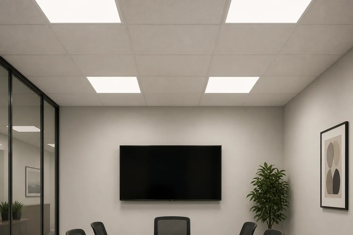
Use the LED lighting sample evaluation checklist to keep model identity, test purpose, acceptance criteria and results together. Record deviations before they disappear into a general “sample approved” status.
Release the Same Configuration You Approved
The review sequence should move from identity to optics, electrical behaviour, thermal conditions and a representative pilot. If the driver, diffuser, LED board, dimensions, mounting kit or control changes, identify which documents and tests are affected before accepting the change.
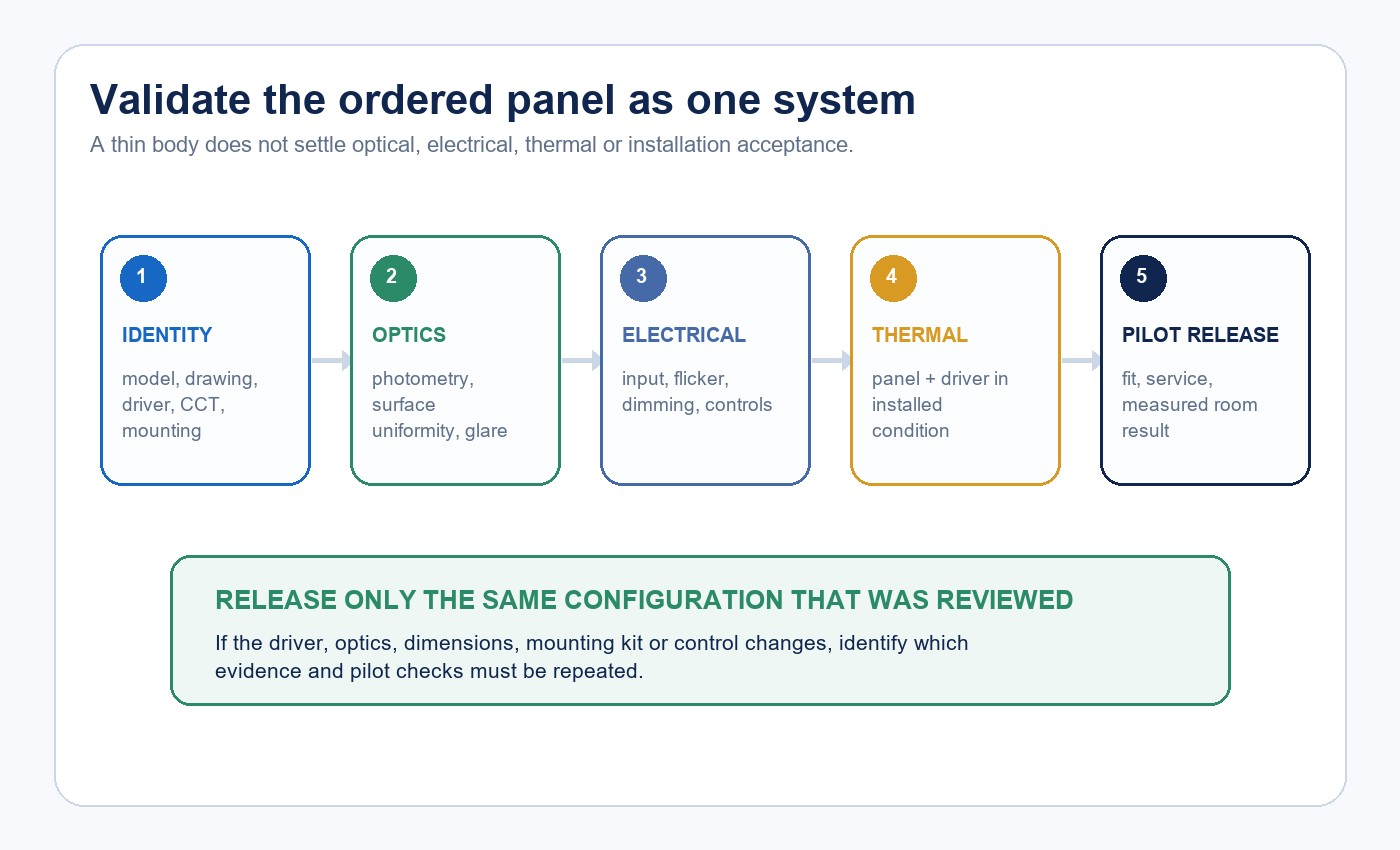
For a broader selection sequence, use the commercial LED panel selection guide. The Project-Grade LED Panels category can then be used to compare current product-family starting points.
Build the Procurement Evidence Set
The RFQ and approval record should identify one ordered configuration rather than a broad family range.
| Freeze before approval | Minimum record | Release question |
|---|---|---|
| Product identity | Model, drawing revision, label and bill-of-material reference | Is production tied to the reviewed configuration? |
| Mechanical interface | Outside dimensions, body height, opening, mounting kit and total clearance | Does it fit and remain serviceable? |
| Optical output | Watts, lumens, photometry, CCT, CRI and glare inputs | Does the room calculation and pilot meet the task? |
| Electrical system | Driver, input, PF, dimming protocol and flicker data | Was the same driver/control combination tested? |
| Thermal boundary | Ambient range, measurement points and installed test condition | Are panel and driver temperatures acceptable? |
| Change control | Controlled substitutions and revalidation rule | What must be repeated when a component changes? |
New Lights can support configuration and sample discussions, but the useful starting input is a bounded project brief. Contact New Lights with the ceiling system, opening, target output, glare requirement, control method, market and expected quantity. The factory and manufacturing overview provides context for production and change-control discussions.
Frequently Asked Questions
Is a backlit LED panel always thicker than an edge-lit panel?
Often, but not universally. Architecture influences the available construction space, while the exact body height comes from the model drawing. Compare products, not labels.
Does panel thickness include the driver?
Not necessarily. Record the panel body, driver enclosure, connectors, cable bends, optional modules and service clearance separately.
Does UGR below 19 mean the installation will have no glare?
No. UGR is a calculated discomfort-glare value for defined photometry, room and observer conditions. Verify the exact input data and run the project layout.
Is a backlit panel automatically more uniform?
No. LED pitch, mixing depth, diffuser, current distribution and manufacturing consistency affect the luminous surface. Evaluate the exact sample and method.
Can every slim LED panel be dimmed?
No. Dimming depends on the exact driver, control method, load range and settings. Test the intended combination at full and low output.
When should a panel sample be repeated?
Repeat affected checks when a change alters the driver, LED board, optics, dimensions, mounting hardware, controls or any condition that supported the original approval.
Editorial Sources
- New Lights, “CCT Dip Switch — Slim & Backlit”: https://www.new-lights.com/product/led-panels-downlight/cct-dip-swith-slim-backlit.html
- International Commission on Illumination, “Calculation and Presentation of Unified Glare Rating Tables for Indoor Lighting Luminaires”: https://www.cie.co.at/publications/calculation-and-presentation-united-glare-rating-tables-indoor-lighting-luminaires
- US Department of Energy, “Flicker Research”: https://www.energy.gov/cmei/ssl/flicker-research