


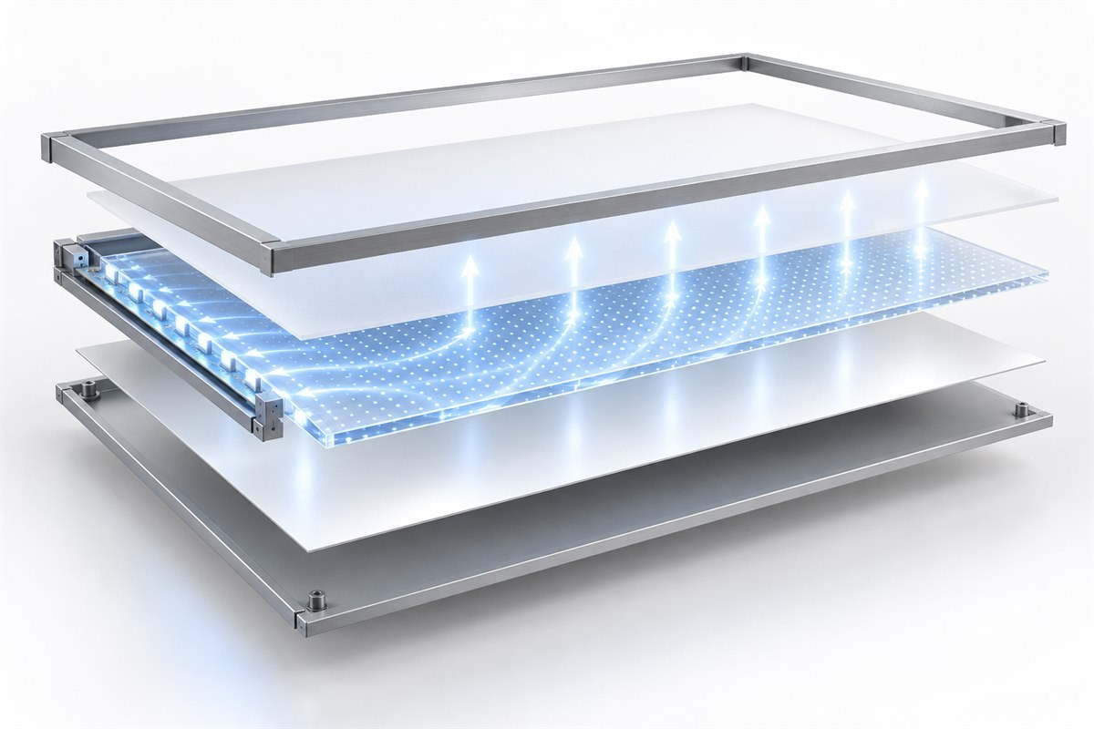
An edge-lit LED panel usually combines a transparent light-guide plate, an extraction pattern, a diffuser, a reflector, edge-mounted LED boards, a frame and thermal path, a rear cover, a driver, wiring and interface materials. The exact polymers, grades, thicknesses and processes vary by design. A buyer should therefore approve the complete material stack and measured panel performance, not accept “acrylic panel” as a sufficient specification.
This article concerns electrically illuminated edge-lit panels. It does not describe roof daylight collectors or artificial-skylight systems. If you first need to distinguish panel-light architectures and component roles, begin with What Is an LED Panel Light?.
Confirm That the Product Is Actually Edge-Lit
In an edge-lit panel, LEDs inject light into one or more edges of a transparent plate. Light travels within the plate, and a controlled pattern redirects part of it toward the useful surface. A diffuser blends local variations, while a rear reflector redirects light that would otherwise leave through the back.
A backlit panel places LEDs behind the diffuser instead of coupling them into the edge of a guide plate. The two architectures can look similar when installed, but they use different optical stacks, depths, thermal arrangements and failure controls. Before discussing materials, identify the architecture from a drawing or disassembled sample.
The edge-lit LED panel product example shows the relevant product family, while the commercial LED panel selection guide covers the wider project decision. Neither link establishes the BOM of an unverified model; the purchase specification must still identify the exact configuration.
Map Every Layer to a Function
The material stack should be reviewed as an interacting optical, mechanical, thermal and electrical system.
| Layer or component | Typical material direction | Primary function | What must be controlled |
|---|---|---|---|
| Front diffuser | Diffusing PMMA, polycarbonate, polystyrene or optical film, depending on design | Blends dots, bands and LED images; shapes output | Grade, thickness, transmission, haze, texture, color and orientation |
| Light-guide plate | Optical PMMA or polycarbonate; some designs use specialty light-guiding grades | Carries light from the edge and releases it across the surface | Grade, thickness, edge finish, flatness, optical loss and extraction pattern |
| Extraction pattern | Printed ink, laser features, machined grooves, molded microstructure or scattering particles | Interrupts guided light in a controlled spatial distribution | Pattern file, density, feature geometry, process tolerance and revision |
| Rear reflector | Reflective white film, sheet, coating or metal-based layer | Returns backward light toward the output surface | Reflectance, flatness, color stability, shrinkage, temperature and assembly |
| LED board | LEDs on metal-core or other suitable PCB | Injects light into the guide edge | Package, bin range, pitch, current, board flatness, position and soldering |
| Frame and thermal path | Often aluminum; steel, polymers or mixed structures may appear | Holds alignment and conducts heat away from the LED edge | Alloy or resin, section, contact area, finish, grounding, corrosion and tolerance |
| Rear cover | Sheet metal or polymer construction | Protects and supports the stack | Stiffness, fire and electrical requirements, venting, finish and fasteners |
| Interfaces | Tapes, adhesives, thermal pads, gaskets, clips and spacers | Position, bond, seal or transfer heat | Exact material code, thickness, cure, aging, optical compatibility and replacement |
Choose the Light-Guide Material by Requirement
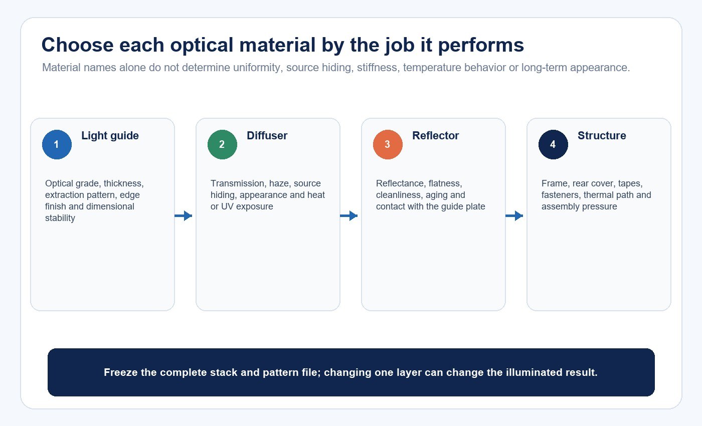
PMMA, commonly called acrylic, is widely available in optical and light-guiding grades. Polycarbonate is also available in transparent, diffusing and light-guide grades. The polymer name alone does not decide the result: grade formulation, processing, thickness, geometry and environment can matter as much as the base resin.
PLEXIGLAS publishes dedicated PMMA grades for edge lighting, backlighting and side lighting. Its edge-lighting technical information describes light entering the sheet edge and being extracted by light-scattering particles. Covestro publishes polycarbonate grades and case studies for molded edge-light guides. These examples show why “PMMA versus PC” is not a complete decision; a generic clear sheet should not be assumed equivalent to a grade designed for light guidance.
| Decision factor | PMMA direction | Polycarbonate direction | Buyer verification |
|---|---|---|---|
| Optical behavior | Optical grades can provide high clarity and low visible-light absorption | Optical PC grades can combine transparency with different mechanical and thermal properties | Obtain grade-specific spectral transmission and finished-panel measurements |
| Impact and handling | Performance depends on grade, thickness, edge quality and mounting | PC is often considered where higher impact resistance is important | Test the actual thickness, support and impact condition |
| Temperature | Check continuous-use temperature, dimensional change and stress from the assembly | Some PC grades are selected for higher-temperature or heat-aging requirements | Measure guide and interface temperatures in the completed panel |
| UV and color stability | Use the declared UV package and application range for the exact grade | Use a UV-stabilized grade where the application requires it | Define exposure, duration and acceptable color/transmission change |
| Processing | Extruded, cast, molded or machined material can behave differently | Flow, molding, stress and drying controls vary by grade and process | Approve process route, edge finish, residual stress and dimensional tolerance |
| Fire and electrical scope | Flammability or safety data are grade- and thickness-specific | Flame-retardant options may exist but can change optics | Match grade, color and thickness to the applicable product evidence |
| Cost and availability | Sheet availability and local fabrication may favor one route | Molded or impact-focused designs may favor another | Compare total stack cost, tooling, yield, lead time and approved alternates |
Do not copy a headline transmission percentage into the finished-panel specification. Material suppliers report properties under defined methods and sample conditions; the assembled panel adds two surfaces, patterns, interfaces, reflectors, diffusers and geometry. Specify the test method and use the result for the exact grade and thickness.
Design the Extraction Pattern With the Whole Panel
The extraction pattern compensates for changing light intensity as light travels away from the LED edge. A uniform field of identical dots is rarely a universal answer. Feature density, size or geometry may need to vary with distance, panel dimensions, one-sided or multi-sided injection, guide thickness, LED pitch, edge coupling and target brightness.
Printing, laser treatment, machining, molding and scattering-particle materials each create a different optical mechanism and process-control problem. The useful question is not “Which process is best?” but “Which process can repeatedly produce the approved luminance distribution, appearance and durability for this design?”
Control the pattern as a released engineering file. A supplier change, panel-size change, LED-board revision or guide-plate substitution can invalidate the pattern even when the product still looks similar when switched off. For size-specific planning, use the LED panel size guide as a separate dimensional reference.
Balance Diffusion, Transmission and Source Hiding
A diffuser must spread local brightness variation without sacrificing more output than the design can tolerate. Increasing haze or thickness may hide extraction dots and edge bands, but can also reduce useful light or alter angular distribution. A higher transmission value does not automatically produce a more comfortable or uniform luminous surface.
The rear reflector has a separate job. It should return light efficiently while remaining flat and stable. Wrinkles, gaps, contamination, shrinkage or discoloration can produce visible patches. If the reflector is bonded, the adhesive and application method become part of the optical system; if it floats, retention and flatness control become critical.
Approve the diffuser, guide and reflector together. Substituting only one layer can move the panel from an acceptable balance to visible dots, a dark center, color nonuniformity or reduced output.
Keep LED Injection and Thermal Control Aligned
The LED package, color coordinates, flux range, drive current, pitch and optical centerline affect how much light enters the plate and how evenly it begins its path. The frame controls the LED-to-guide gap and edge alignment. Even a small position change can create a bright band, dark edge or production variation.
Thermal design is coupled to optics. Higher LED temperature can change output, color and component life. An aluminum frame may provide a useful heat path, but the word “aluminum” proves little without the section, contact area, interface material, mounting and operating condition. Measure temperatures at defined LED-board, frame, driver and interface locations after stabilization.
The driver is part of the configuration as well. A current change can alter brightness, heat, uniformity and flicker. If dimming is offered, review the panel at the required dimming points rather than only at full output.
Control Assembly and Material Changes
Production consistency depends on more than a BOM. Plate handling, cleaning, edge preparation, dust control, pattern registration, film removal, reflector placement, LED alignment, frame pressure and final inspection can all alter the illuminated appearance.
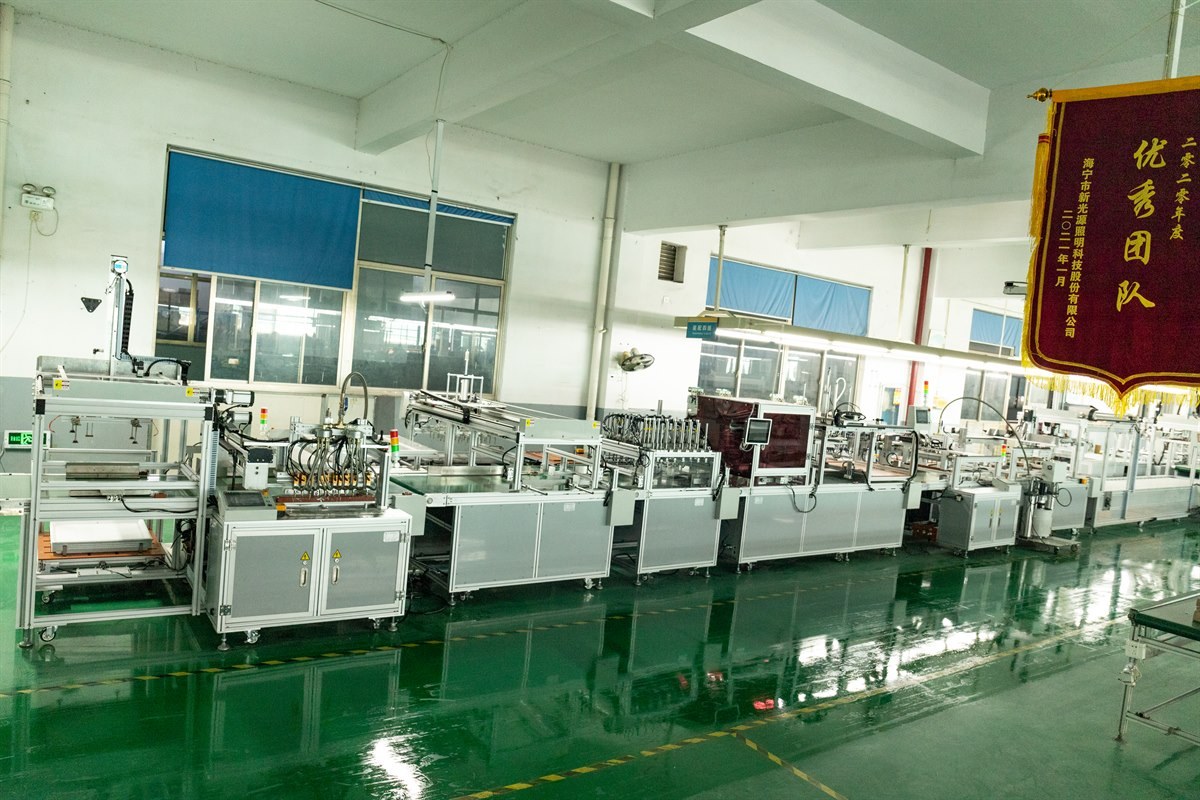
The wider LED panel manufacturing guide explains the process sequence. For this material-focused decision, require lot traceability and change notification for the guide plate, diffuser, reflector, LED board, driver and interface materials. An “equivalent” substitute should not enter production until the affected optical, thermal, mechanical and safety checks are repeated.
Diagnose Defects Through the Stack
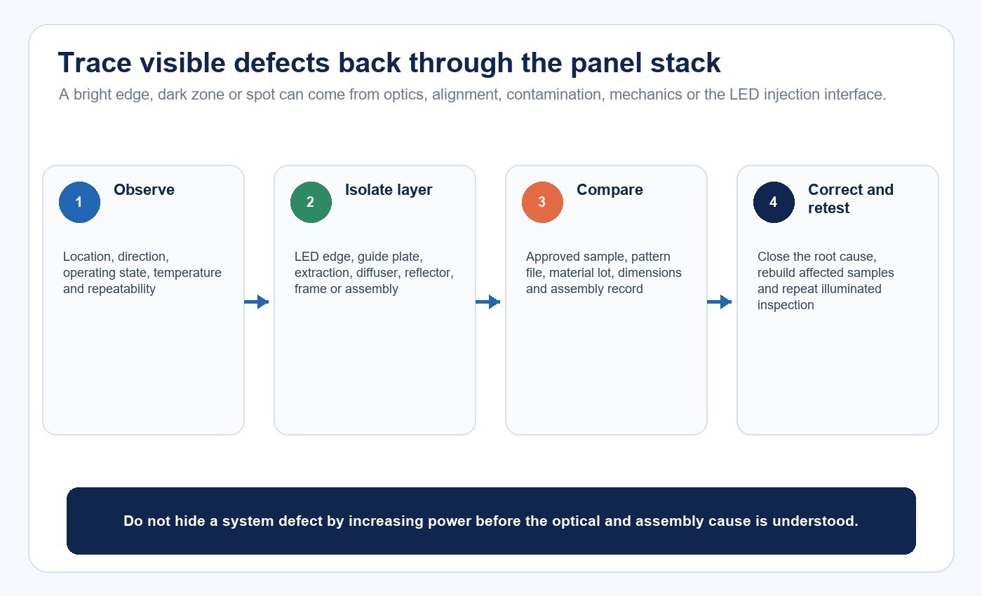
When a sample fails, the visible symptom rarely identifies a single material automatically.
| Observed symptom | Plausible causes | Useful next checks |
|---|---|---|
| Bright edge, dark center | Pattern density too low away from LEDs, poor guide material match, one-sided injection loss | Review pattern map, edge coupling and center-to-edge luminance |
| Visible dots or LED images | Diffuser hiding power, LED pitch, guide pattern or spacing mismatch | Compare diffuser grade/orientation and inspect at defined distance and angle |
| Patchy or cloudy areas | Dust, fingerprints, reflector wrinkles, adhesive marks, plate stress or surface damage | Inspect layers separately under controlled lighting and trace assembly station |
| Color variation across panel | LED bin spread, temperature gradient, optical-layer spectral effects or current imbalance | Map chromaticity and temperature at corresponding locations |
| Warping or gaps | Thermal expansion, frame tolerance, rear-cover stiffness, adhesive creep or assembly pressure | Measure flatness before and after thermal operation |
| Output changes after aging | LED depreciation, polymer color shift, reflector change, adhesive degradation or driver drift | Compare electrical, spectral, luminance and visual records to the approved baseline |
Avoid solving every uniformity problem by increasing diffuser opacity or LED power. Those changes can hide one symptom while reducing efficacy or raising temperature. The corrective action should follow a cause-and-effect test.
Build a Repeatable Sample-Acceptance Method
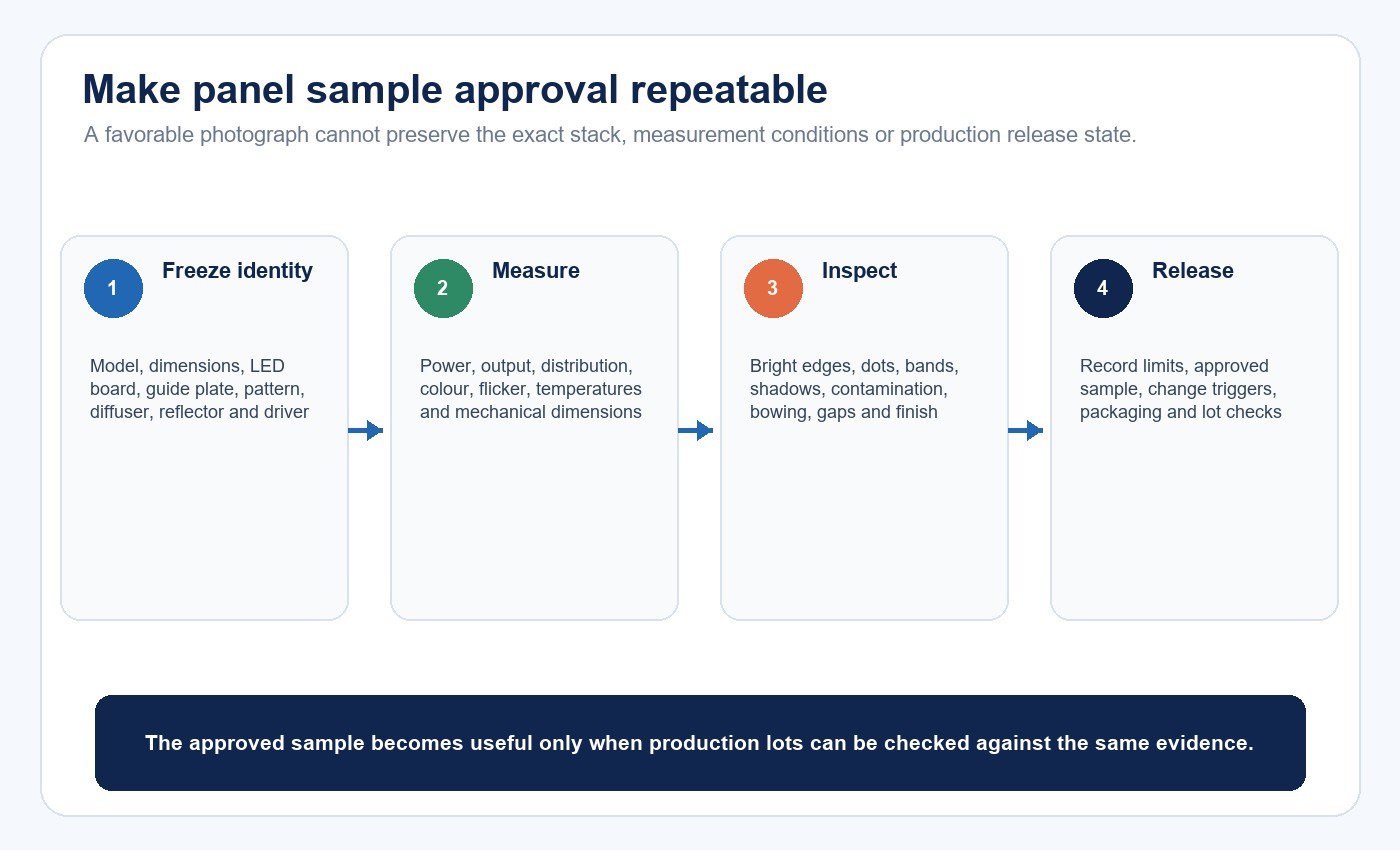
The sample must identify the exact panel size, material grades, thicknesses, pattern revision, LED board, bin range, drive condition, frame, reflector, diffuser, interfaces and assembly route. A photograph alone cannot preserve that configuration.
Measure a defined grid across the luminous surface. Record average and minimum luminance or illuminance, uniformity calculation, color coordinates, input power and critical temperatures under stated ambient, stabilization time, instrument and geometry. Add a visual review at the real viewing distance for edge bands, dots, scratches, particles, bubbles, light leakage, frame gaps and finish.
Use the LED lighting sample evaluation checklist to structure the broader approval record. The acceptance result should state both pass limits and exceptions. Retain the approved data package and sample reference, then repeat affected tests after controlled changes.
Verify Safety and Performance Evidence at Product Level
Optical material data do not certify the luminaire. UL Solutions identifies UL 1598 for luminaires and UL 8750 for LED equipment used in lighting products. IEC 60598-1:2024 covers general luminaire safety requirements, while IEC 62722-2-1:2023 covers performance requirements and test conditions for LED luminaires. The actual route depends on product type, market, installation and certification scope.
Match every certificate, listing, report and component record to the exact model, factory, ratings and construction. A recognized component can support a design, but it does not by itself establish certification of the assembled panel. Material grades and thicknesses that affect fire, electrical, thermal or mechanical compliance should be controlled within the approved construction.
Write the RFQ Around Decisions and Evidence
Provide the product architecture, dimensions, optical target, viewing condition, mounting, environment, input, controls, market and quantity. Ask the supplier to return a layer-by-layer BOM with material manufacturer, grade, thickness, process, approved alternates and evidence references.
The RFQ should also define pattern ownership and revision, LED bin range, driver, thermal limits, test grid, uniformity method, visual defects, sample quantity, change-control procedure and release records. This makes price comparison meaningful because suppliers are quoting the same controlled configuration.
If the product identity or stack is still uncertain, contact New Lights with the panel architecture, dimensions, optical targets, environment and available drawings. The next step should be a bounded configuration review, followed by a representative sample—not an assumption based on the word acrylic.
Frequently Asked Questions
Is PMMA always the best material for an edge-lit panel?
No. Optical PMMA is common, but the decision depends on grade, thickness, panel geometry, impact, temperature, UV exposure, process, safety scope, cost and the measured finished-panel result.
Is polycarbonate always more durable than acrylic?
Not in every meaning of durability. Impact, scratch resistance, heat aging, UV behavior, chemical exposure, stress and dimensional stability are different properties. Compare the exact grades under the intended conditions.
Does a clear acrylic sheet guarantee high panel efficiency?
No. Guide loss, edge coupling, extraction pattern, reflector, diffuser, LED placement and interfaces all affect useful output. Material transmission is only one input.
Is laser engraving better than printing the extraction pattern?
Neither process is universally better. Compare pattern precision, repeatability, surface condition, tooling, throughput, cost and finished-panel uniformity for the actual design.
What should trigger sample revalidation?
Changes to the guide plate, thickness, pattern, diffuser, reflector, LED package or bin, drive current, frame, adhesive, tooling, supplier or assembly process should trigger the affected optical, thermal, mechanical and safety checks.
Editorial Sources
- POLYVANTIS, “PLEXIGLAS LED for edge lighting — Technical Information”: https://www.plexiglas.de/files/plexiglas-content/pdf/technische-informationen/212-15-EN-PLEXIGLAS-LED-edge-lighting.pdf
- Covestro, “Makrolon for LED Lighting”: https://www.covestro.com/-/media/covestro/solution-center/brands/downloads/imported/1585569908.pdf
- UL Solutions, “Indoor and Decorative Lighting”: https://www.ul.com/services/indoor-and-decorative-lighting
- IEC, “IEC 60598-1:2024 — Luminaires — Part 1: General requirements and tests”: https://webstore.iec.ch/en/publication/66620
- IEC, “IEC 62722-2-1:2023 — Luminaire performance — Particular requirements — LED luminaires”: https://webstore.iec.ch/en/publication/66361












