


The best emergency light source is the one that forms part of an approved, reliable and maintainable system for the building. LED is now a common source because it can start quickly, use compact optics and operate efficiently, but source technology alone does not establish emergency performance. Selection must connect the life-safety task, applicable rules, emergency light distribution, power architecture, transfer behavior, duration, product evidence, testing and maintenance.
A practical workflow is: define what occupants or workers must be able to do after normal lighting fails; confirm the jurisdiction and design criteria; choose the power architecture; verify the exact emergency configuration; calculate and test emergency-mode illumination; then commission and maintain the installed system. Skipping any one of these stages can leave a system that lights during a brief demonstration but fails its real purpose.
Begin With the Life-Safety Task and Jurisdiction
Emergency lighting is not one function. The project may need to illuminate an escape route, reduce panic in an open area, support the safe shutdown of a hazardous process, identify fire or first-aid equipment, illuminate an exterior discharge path, or keep an exit sign visible. Each task creates different placement, distribution, duration and reliability questions.
Map the route and decision points: occupied areas, aisles, stairs, changes of direction, intersections, doors, final exits, exterior discharge, refuge areas and high-risk work. Record obstructions, rack heights, changes in floor level, expected occupants, accessibility needs and likely smoke or power-failure conditions that the responsible design team must consider.
In the United States workplace context, OSHA 29 CFR 1910.37 requires exit routes to be adequately lighted and safeguards such as exit lighting to remain in proper working order. That requirement is one part of the project boundary, not a complete emergency-lighting calculation. The responsible designer and authority having jurisdiction must identify the adopted building, fire, electrical and life-safety requirements for the actual occupancy.
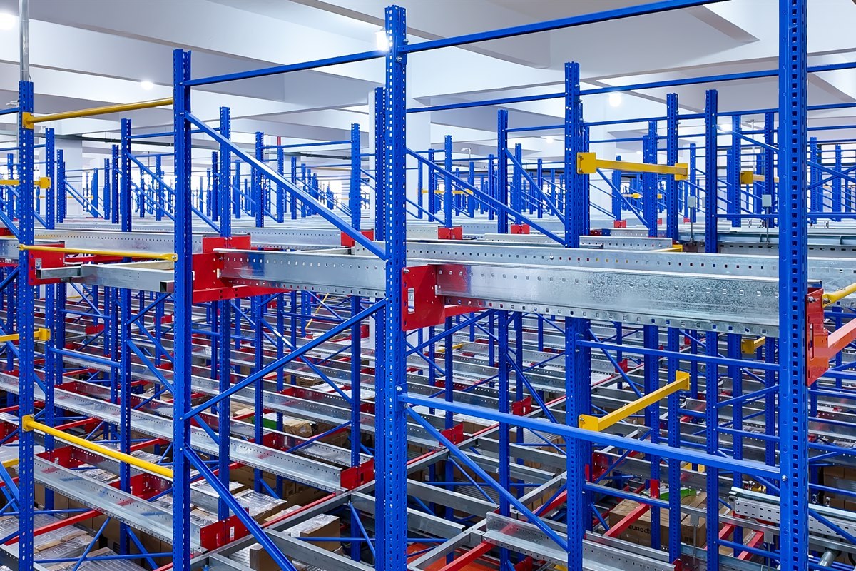
The industrial and warehouse lighting solution provides the wider application context for normal task lighting, circulation, racking and controls. Emergency performance still requires its own design basis and evidence.
Specify Emergency Performance Before Choosing Equipment
Define the outputs that the system must deliver when normal power is unavailable. Depending on the project, these may include minimum and average illumination, uniformity, vertical visibility, sign luminance, operating duration, transfer behavior, maintained or non-maintained operation and performance for high-risk tasks. Use the applicable project rules for exact values.
Photometric evidence must represent emergency mode. A luminaire that produces several thousand lumens on normal power may operate at a small fraction of that output from a battery or emergency driver. Distribution can also change when only selected luminaires or LED channels remain energized. Normal-mode photometry, a family brochure or a wattage label cannot be substituted for emergency-mode data.
For each candidate, request the emergency output, intensity distribution or photometric file, mounting position, orientation, spacing assumptions, operating mode, battery or central-supply condition and the maintenance factors used in the design. Calculate the route and critical points with the exact emergency configuration, then plan measurements during commissioning.
Compare Power Architectures as Systems
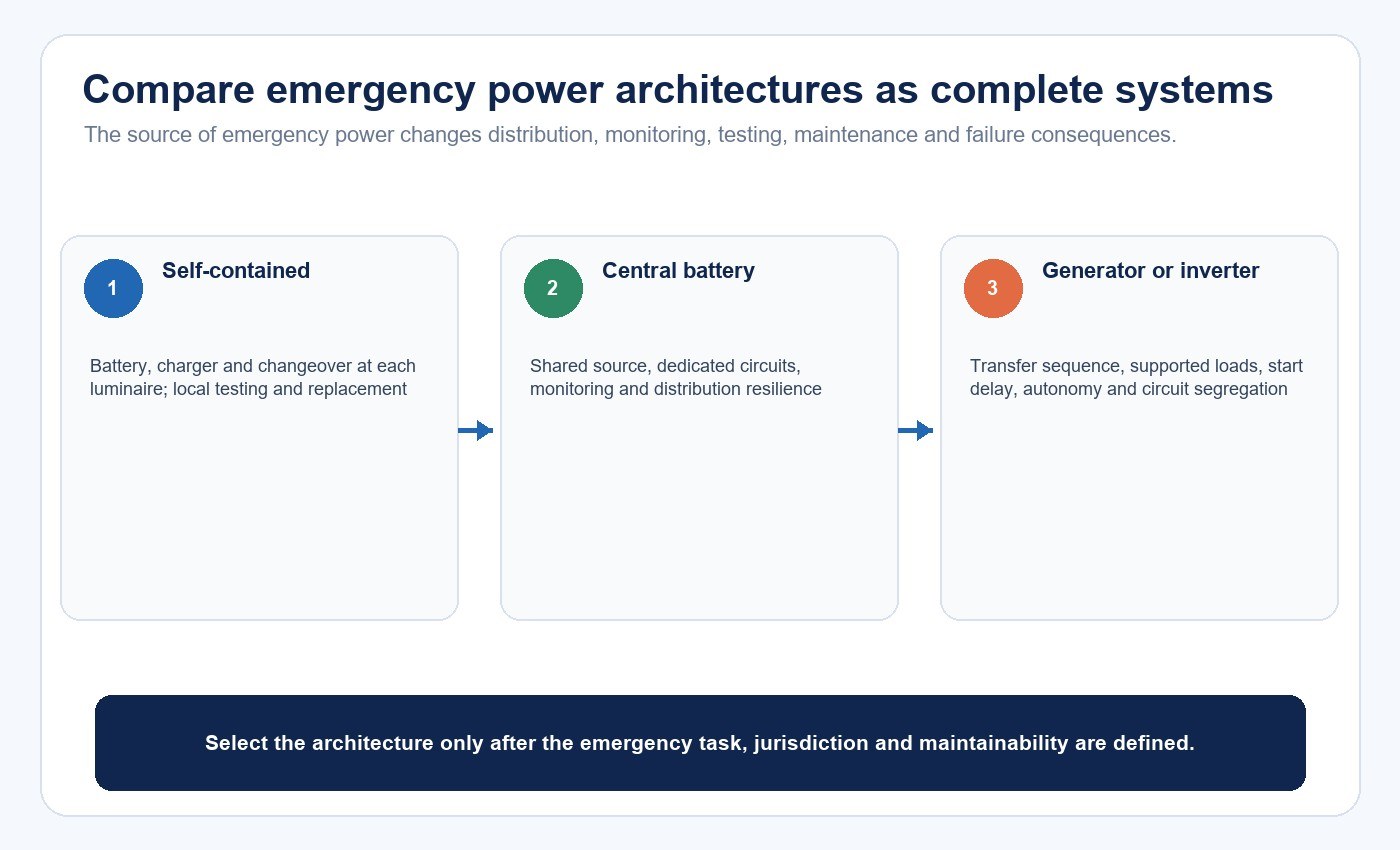
The power source affects wiring, monitoring, fault containment, maintenance and future replacement. Compare the complete architectures rather than treating “battery backup” as one generic option.
| Architecture | Where emergency energy is stored | Main advantages | Main coordination risks | Best-fit questions |
|---|---|---|---|---|
| Self-contained luminaire | Battery and charger are integral or locally connected | Local independence; limited emergency distribution wiring | Many batteries to inspect; ceiling temperature; access; inconsistent replacement | Can every unit be tested and serviced safely? Are ambient and duration conditions covered? |
| Central battery system | A central safety power source feeds multiple emergency circuits | Centralized batteries, monitoring and service | Protected distribution, system capacity, single-point faults and compatible luminaires | Are circuits, monitoring, autonomy and fault zones coordinated? |
| Inverter or UPS arrangement | Central conversion/storage supplies designated loads | Can support selected normal luminaires or broader critical loads | Load compatibility, waveform, inrush, dimming state, capacity and transfer | Is every connected luminaire and control state verified on the supply? |
| Generator-supported system | Engine generator or other standby source supports emergency distribution | Long-duration capability where designed and fueled accordingly | Start/transfer sequence, interim illumination, fuel, testing and distribution | What supplies light before the generator is available, and which faults are simulated? |
| Hybrid system | Two or more local and central sources | Can separate critical zones and improve resilience | More interfaces, test scenarios and ownership boundaries | Does each zone have a clear failure sequence and maintenance owner? |
First cost is only one variable. Estimate inspection labor, battery replacement access, monitoring, spare parts, circuit testing, room requirements, fault isolation, expansion and the consequences of a common-mode failure. A central system can simplify battery service but increase dependence on protected distribution; self-contained units distribute risk but can create hundreds of local maintenance points.
Define the Failure Sequence, Not Only the Normal Diagram
Emergency systems respond to failures. The design team should therefore document which loss of supply initiates emergency operation, what controls are overridden, how output changes, which alarms appear and how the system returns to normal service. Consider local branch failure as well as a whole-building outage.
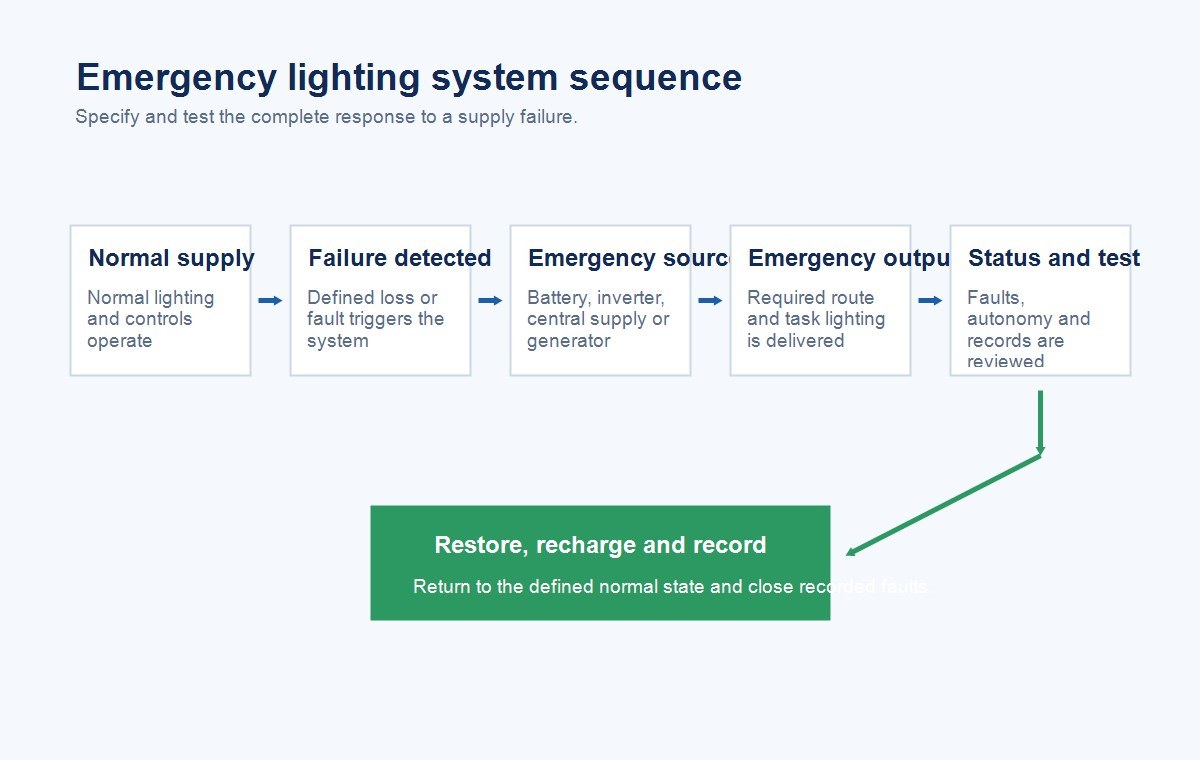
The system narrative should answer several second-order questions. If a control network fails while normal power remains available, can it suppress required emergency output? If one circuit fails, does the sensing arrangement detect the loss seen by occupants? If a battery is disconnected, is the fault visible? After a duration test, how is reduced readiness during recharge managed? If a software update changes control behavior, who repeats the emergency tests?
The related guide to connected lighting and controls in commercial specifications explains how sequences, overrides, communication-loss states and commissioning records can be defined before procurement.
Distinguish Maintained, Non-Maintained and Combined Operation
A maintained emergency luminaire operates during normal conditions and continues, or changes output, on emergency power. A non-maintained unit is normally off and illuminates when the monitored normal supply fails. Combined and switched-maintained arrangements can introduce additional circuits and control states.
The operating mode affects normal energy use, driver temperature, battery loading, wiring, dimming and test behavior. Define the monitored supply, normal command state, emergency override, emergency output and return-to-normal sequence. A maintained luminaire that is dimmed during normal occupancy may need a defined emergency command independent of the dimming network.
Exit signs, directional information and escape-route luminaires should also remain separate schedule items where their functions differ. A bright general luminaire does not replace the visibility and directional role of an exit sign, while an illuminated sign does not provide the floor-level distribution needed along a route.
Verify the Complete Emergency Configuration
UL Solutions describes UL 924 as the Standard for Emergency Lighting and Power Equipment in North America and lists equipment such as emergency luminaires, exit signs, power sources and supporting controls. IEC currently lists IEC 60598-2-22:2021, edition 5.0, for emergency luminaires within its scope. Destination-market adoption, certification route and project applicability still need confirmation.
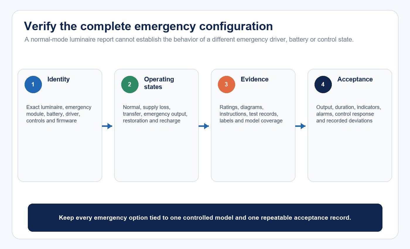
Do not verify only the visible luminaire. The emergency configuration may include a driver, battery, charger, indicator, test switch, wiring harness, remote enclosure, control device and instructions. A normal luminaire combined with an emergency driver is not automatically an approved emergency assembly. The pairing, emergency output, temperatures, wiring, charging, controls, enclosure and markings must be covered by the responsible evidence and installation method.
Use a model-bound evidence matrix:
| Evidence item | Required match | What the reviewer should verify | Release blocker |
|---|---|---|---|
| Listing or certificate | Exact model, suffix, standard, factory and status | Official issuer record, scope, ratings and conditions | Similar model or logo only |
| Emergency photometry | Exact emergency output, optic and mounting | File identity, operating state, distribution and calculation inputs | Normal-mode data substituted |
| Battery and charger | Part number, chemistry, capacity, temperature and charging route | Duration basis, recharge, protection, replacement and status indication | Unapproved substitute or missing end-of-life basis |
| Controls and transfer | Exact devices, wiring and programmed states | Failure detection, override, transfer, restoration and communication-loss behavior | Emergency command depends on an unverified control state |
| Environmental evidence | Complete enclosure and installation condition | Ambient, damp/wet exposure, ingress, condensation, orientation and cable entries | Rating applies only to one component |
| Instructions and labels | Delivered configuration and destination | Wiring, test method, restrictions, marks, model and battery information | Label, certificate and quotation disagree |
The LED product compliance document checklist provides a broader method for linking declarations, reports, labels and instructions to the purchase-order model. If the normal-lighting concept includes panels, the commercial LED panel selection guide and a published product page such as the IP65 Backlit LED Panel can support that separate decision; emergency suitability must still be specified for the exact configuration.
Evaluate Battery, Charger and Ambient Conditions Together
Battery chemistry alone does not determine suitability. Review the required duration under the applicable test basis, capacity over service life, charger behavior, recharge time, ambient and enclosure temperature, storage, transport, protection, replacement access and approved substitutes. A physically compatible replacement can still differ in capacity, protection, temperature range or approval status.
Temperature deserves special attention. A battery mounted inside a warm ceiling luminaire may experience different conditions from room air. Cold areas can reduce available capacity and affect charging. The luminaire, battery, charger and controlgear must be evaluated as one emergency configuration at the project’s credible operating conditions.
Define what the indicators mean and where they can be seen. A status light can report a defined condition, but maintenance personnel still need a procedure for functional tests, duration tests, physical inspection, fault response and record review.
Plan Testing and Maintenance Before Procurement
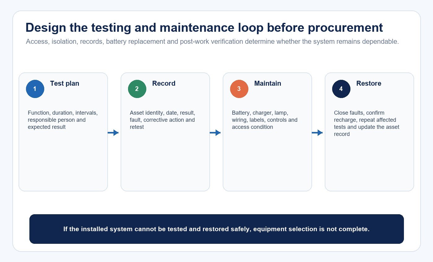
Emergency lighting is unusual because long periods of apparent normality are followed by a short period in which performance matters critically. The maintenance system is therefore part of selection. Decide who performs tests, how units are accessed, what automatic testing or central monitoring records, how faults are escalated and how quickly failed components can be replaced.
Commissioning should verify normal and emergency operation, the correct failure signals, transfer, maintained behavior, route illumination, sign visibility, alarms, monitoring, required duration, restoration and recharge. Test local circuit failures and control failures that are relevant to the design, not only a convenient whole-building switch-off.
Changes after handover can invalidate the original result. New racks, partitions, equipment, locked doors or altered routes can block light and visibility. Battery replacement, driver substitution, firmware changes and control reprogramming should trigger a defined review and retest.
Use a Representative Pilot for Retrofit Projects
For a warehouse retrofit, select a pilot zone that contains the difficult conditions: a long rack aisle, an intersection, a level change, a final exit or an area with controls. Document the existing circuit, emergency source, luminaire identity, mounting, obstructions and test points before changing equipment.
Install the proposed emergency configuration exactly as it would be ordered. Measure the required points in emergency mode, observe transfer and controls, complete the required duration procedure, inspect indicators and fault reporting, then confirm service access. The LED lighting sample evaluation checklist can preserve the model, test conditions, measurements and acceptance criteria.
The pilot is not the rollout approval by itself. Compare the test zone with the rest of the site and identify which fixtures, circuits, control systems, temperatures or obstructions are different. The New Lights factory and manufacturing overview provides context for discussing controlled configurations, samples and release records once the project evidence requirements are defined.
Build the Emergency-Lighting RFQ Around Evidence
Provide the jurisdiction, occupancy, emergency tasks, route drawings, mounting, environment, normal and emergency power architecture, operating mode, duration criteria, controls, monitoring, testing and required approvals. Ask suppliers to return an evidence index tied to the exact offered configuration.
The response should identify the model and suffix, certification or listing, applicable standard, emergency output and photometry, battery and charger, transfer behavior, duration test basis, ambient limits, wiring, controls, indicators, test method, factory, instructions and unresolved exceptions. Keep missing or conditional items open rather than converting them into a pass.
To review a bounded project, contact New Lights with the destination market, building use, route plan, emergency tasks, power strategy, operating conditions and evidence list. Product recommendations should follow those inputs, not precede them.
Frequently Asked Questions
Is LED always the best source for emergency lighting?
No. LED is commonly suitable, but the decision depends on emergency output, optics, power architecture, duration, environment, approval, controls, testing and maintenance of the complete system.
Is a self-contained battery luminaire better than a central system?
Neither is universally better. Compare building scale, protected wiring, monitoring, maintenance access, environmental conditions, fault isolation, replacement work and life-cycle cost.
Can a normal LED luminaire use any emergency driver?
No. The luminaire, driver, battery, wiring, output, thermal conditions, controls, labels and approval scope must form a documented and permitted configuration.
How long must emergency lighting operate?
The required duration depends on the jurisdiction, occupancy, system and project rules. Confirm the governing requirement and the test basis instead of applying one value globally.
Does automatic self-testing eliminate maintenance?
No. Automatic testing can perform and record defined checks, but faults still require action, records require review, physical conditions need inspection and the illuminated route must remain suitable.
Editorial Sources
- Occupational Safety and Health Administration, “29 CFR 1910.37 — Maintenance, safeguards, and operational features for exit routes”: https://www.osha.gov/laws-regs/regulations/standardnumber/1910/1910.37
- Occupational Safety and Health Administration, “Emergency Preparedness and Response: Getting Started”: https://www.osha.gov/emergency-preparedness/getting-started
- UL Solutions, “Emergency Lighting Testing and Certification”: https://www.ul.com/services/emergency-lighting-testing-and-certification
- IEC, “IEC 60598-2-22:2021 — Luminaires — Part 2-22: Particular requirements — Luminaires for emergency lighting”: https://webstore.iec.ch/en/publication/61770












