


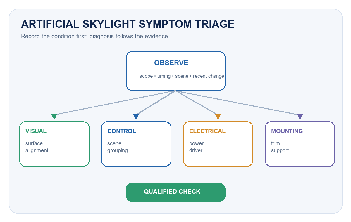
Artificial skylight troubleshooting should begin with the visible symptom, the exact product series and the operating configuration—not with a replacement part. Record whether the problem affects one module, one zone or the whole installation; whether it is constant or intermittent; and what changed before it appeared. That evidence usually separates a visual-surface issue from a mounting, power, driver or control problem.
An artificial skylight is an architectural lighting system that creates a daylight-inspired ceiling or wall effect in spaces with limited natural light. It is not a photovoltaic laboratory solar simulator. The maintenance priorities are therefore visual consistency, secure installation, reliable power and control, clean optical surfaces, accessible service components and a documented return to operation.
Start With the Symptom and the Exact Configuration
Before opening a ceiling or changing a setting, identify the installed family, model, quantity, circuit, control method and last known good condition. Photograph the affected area from the same viewpoint under the same scene and ambient-light conditions. Note recent ceiling work, cleaning, power interruptions, control updates, occupancy changes or water ingress nearby.
This first record prevents a common maintenance mistake: treating every visual complaint as a failed light source. A sky effect that looks uneven may come from dust, a shifted optical surface, a changed scene, reflected ambient light or one module operating differently from the rest. Intermittent output may be linked to a connector, driver, thermal condition or control command. The symptom is the starting point; it is not the diagnosis.
The Artificial Skylight & Daylight solution overview helps identify the intended application and format. For projects still at the design or mock-up stage, use the artificial skylight project planning guide instead; this article focuses on systems already installed or being handed over.
Use a Symptom-to-System Matrix
The table below is a triage tool, not a substitute for the model instructions. Facilities staff can collect the observations; opening electrical compartments, testing conductors or changing safety-critical mounting should be assigned to qualified personnel under the applicable site procedure.
| Observed symptom | System area to review | Safe first check | Evidence for escalation |
|---|---|---|---|
| Uneven, dull or patchy sky effect | Optical face, scene setting, module alignment, ambient reflections | Compare clean surfaces and active scenes across adjacent modules | Same-view photographs, affected module IDs, scene name and time |
| Wrong color or inconsistent scene | Controller, grouping, saved scene or module configuration | Confirm the selected scene and whether all modules received the command | Controller screenshots, group map, firmware/configuration record |
| Flicker, pulsing or intermittent output | Supply, connector, driver, dimming path or control communication | Record when it occurs and whether it follows a scene, load or restart event | Short video, circuit/zone, operating level, restart history |
| One module is off | Local supply, connection, driver, address or module fault | Check the approved control interface and compare zone status | Model/serial, circuit status, error log and swap-test result if authorized |
| Repeated shutdown, heat or unusual noise | Ventilation, driver loading, loose component or abnormal operating condition | Stop normal use if safety is in doubt and protect the area | Temperature/odor/noise observations, installation photos, service history |
| Trim movement, ceiling gap or enclosure shift | Fixings, support frame, safety retention or ceiling interface | Restrict access below if movement could create a falling-object risk | Opening dimensions, support details and photographs above/below ceiling |
When the Sky Effect Looks Uneven or Flat
Begin with repeatable viewing conditions. Use the same control scene, camera position and nearby ambient-light condition. Compare the affected unit with an adjacent known-good unit rather than with a brochure image. Clean only with the method approved for the visible material; aggressive chemicals, abrasive cloths or excess liquid can alter the surface or enter the assembly.
If cleaning does not resolve the difference, inspect from outside the enclosure for obvious trim displacement, panel movement or inconsistent alignment. A modular installation can also appear uneven when adjacent units use different scenes or output levels. Do not compensate for an alignment or configuration problem by arbitrarily increasing output. Record the finding and restore the intended mechanical or control state.
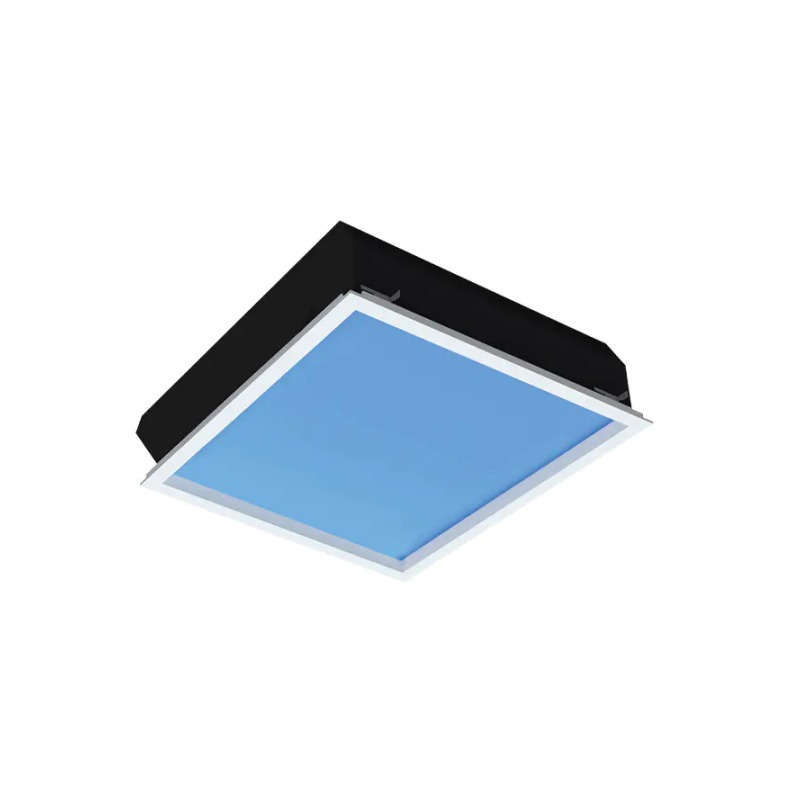
For a recessed project, the E Series artificial skylight family provides another example of a deeper enclosure whose visible effect and above-ceiling service space must be considered together. The correct fix depends on the exact construction, not only the appearance from the room.
When Color or Scene Behavior Is Wrong
Confirm the user interface, active scene, group membership and restart behavior. Ask whether the issue began after a controller replacement, software update, power outage or space reconfiguration. If multiple modules should act as one visual ceiling, compare their stored settings and addresses before replacing hardware.
Control faults often look like optical faults. One unit may be following a different group, remaining at a previous level or returning to a default scene after power restoration. Capture the current configuration before making changes so the team can reverse an unsuccessful adjustment. The LED driver, dimming and control compatibility guide explains why the driver, control method and command path must be treated as one system.
When Output Flickers, Drops or Becomes Intermittent
Flicker or intermittent operation should be documented at the exact operating state where it appears. Note the dimming level, scene, time since start-up, other loads on the circuit and whether the event affects one unit or a whole zone. A phone video can help establish timing, but electrical measurements should be made with suitable instruments by qualified personnel.
Avoid repeated random resets. They can erase the sequence that would have identified a control, connection, power or thermal trigger. Preserve controller logs and error messages, then compare the installed driver and control configuration with the approved submittal. If the complaint is specifically about visible modulation or electrical quality, use the flicker, power factor and THD buyer checklist to define the measurement request.
When Heat, Noise or Repeated Shutdown Appears
Unexpected heat, odor, noise or repeated protective shutdown requires a conservative response. Stop normal operation when continued use could damage equipment or create a safety concern, isolate the affected area under the site procedure and involve qualified service personnel. Do not defeat protection, enlarge ventilation openings without approval or substitute a driver because its nominal wattage appears similar.
Check whether insulation, stored material, ceiling changes or displaced cabling has reduced the intended service space around the enclosure or driver. Confirm that replacement parts match the exact electrical, control, thermal and mechanical requirements. The LED thermal management and lifetime validation guide provides a separate framework for evaluating thermal evidence without turning an observed hot spot into a universal lifetime conclusion.
Check the Ceiling, Trim and Service Access
Artificial skylights are part of the ceiling system as well as the lighting system. Review the visible trim, cutout, support frame, suspension or fixing hardware, safety retention and cable routing. If a module has shifted, determine whether the ceiling interface, independent support or service activity caused the movement.
Large or modular formats may require access above the ceiling and a planned removal path. Do not let later trades block the driver, controller, junction point or maintenance opening. The P Series modular artificial skylight illustrates why the module grid, supporting structure, cable route and service access need to be recorded as one installation package.
Separate Cleaning From Electrical Service
Routine cleaning and observation can be scheduled separately from intrusive service. A cleaning visit should record the surface condition, room use, contamination source and before/after appearance. Electrical or control service should record isolation, test method, settings, replaced parts and the person responsible for returning the system to operation.
CIE’s indoor-lighting maintenance guidance notes that dirt accumulation, equipment aging, environmental conditions and operating conditions all affect light depreciation. That supports a site-specific schedule rather than one universal interval. A clean office, a dusty circulation space and a high-access ceiling can justify different inspection frequencies even when they use the same product family.
Coordinate stock and service planning with the lighting maintenance and spare-parts planning guide. Keep exact approved spares, not merely parts that look compatible. Record driver, controller, connector and optical-component revisions so a future replacement does not introduce a visible or control mismatch.
Verify the Result After Any Intervention
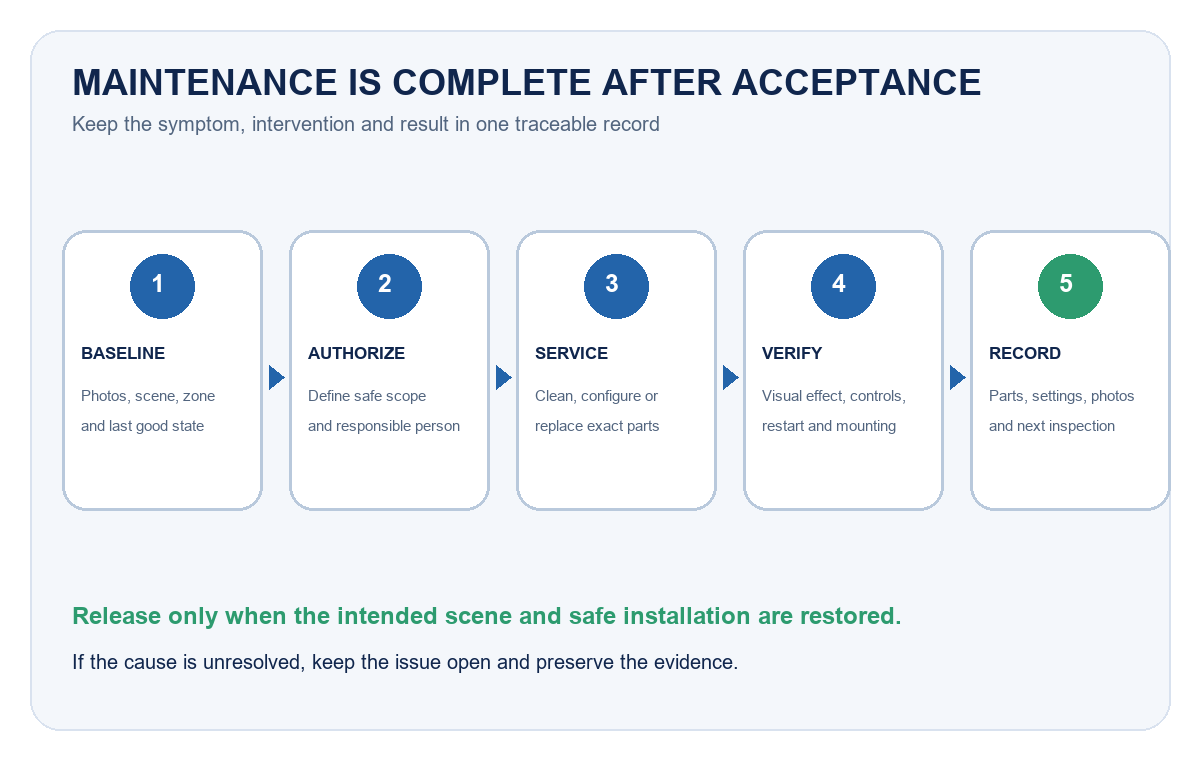
Maintenance is complete only when the intended visual effect, controls and safety conditions have been checked again. Use the same scene and viewing conditions captured before service. Test normal commands, restart behavior and any approved dimming or grouping functions. Confirm that trims, access panels, safety retention and ceiling finishes have been restored.
| Maintenance event | Minimum record | Post-service acceptance |
|---|---|---|
| Cleaning optical or visible surfaces | Area, method, material used, before/after photos | Uniform appearance under the same scene; no residue or damage |
| Adjusting scenes or grouping | Previous settings, changed values, affected zones, backup file | Correct response from every intended module; restart behavior confirmed |
| Replacing driver, controller or module | Exact old/new part IDs, reason, installer, wiring/configuration record | Stable operation across required scenes; no new mismatch or abnormal behavior |
| Correcting trim, support or access | Opening/support details, fasteners or retention restored, photos | Secure alignment, protected cabling and usable future service access |
| Investigating intermittent behavior | Trigger conditions, logs, measurements and actions | Observation period completed without recurrence under the recorded conditions |
Frequently Asked Questions
How often should an artificial skylight be cleaned?
Set the interval from the room environment, access conditions, visible contamination and the manufacturer’s instructions. Start with an inspection baseline, then shorten or extend the cycle using actual condition records rather than a universal calendar rule.
Can facilities staff reset a controller when one panel looks different?
They can follow an approved user-level procedure, but they should first record the scene, group and symptoms. Repeated resets can remove useful evidence or change a working configuration. Escalate changes that require service access, wiring or hidden settings.
Does flicker mean the LED module has failed?
Not necessarily. The cause may be in the supply, connection, driver, dimming path, control communication or module. Record the operating state and scope, then test the complete path with qualified personnel.
Can a similar-wattage driver be used as a replacement?
Wattage alone is not enough. Verify output characteristics, control method, protection, connectors, thermal suitability, mechanical fit and the exact approved system configuration before substitution.
What should be included in an artificial skylight handover file?
Include model and quantity, layout, circuits, control groups and scenes, approved submittals, installation photos, driver/controller locations, service-access method, cleaning guidance, spare-parts list, configuration backup, warranties and an issue log.
Build the Maintenance File Before Handover
A useful handover file lets a future technician identify the system without dismantling it. Mark every module and zone consistently across the ceiling plan, controller and service record. Store the approved product data, configuration export, access instructions and photographs of concealed components. Record the acceptance scene and camera viewpoint for visually sensitive spaces.
When the exact model or service boundary is unclear, gather the opening dimensions, ceiling depth, room photographs, control requirement and installed labels before requesting support. The New Lights sample-evaluation checklist can structure a controlled comparison when a replacement sample is required. For a model-level review, contact New Lights with the evidence package rather than only a symptom description.
Editorial Sources
- CIE, Guide on the Maintenance of Indoor Electric Lighting Systems, 2nd ed. (CIE 97:2005): https://www.cie.co.at/publications/guide-maintenance-indoor-electric-lighting-systems-2nd-ed
- IEC, IEC 60598-1:2024 — Luminaires — Part 1: General Requirements and Tests: https://webstore.iec.ch/en/publication/66620
- U.S. Department of Energy, Lighting Controls Solutions: https://www.energy.gov/cmei/ssl/lighting-controls-solutions
- U.S. Department of Energy and GSA, LED Lighting and Controls Guidance for Federal Buildings: https://integratedlightingcampaign.energy.gov/sites/default/files/2024-10/LED%20and%20Controls%20Guidance%20for%20GSA_0.pdf












