


An artificial skylight is an electric luminous ceiling system. Plan it by defining the intended visual experience, then coordinate module geometry, surrounding lighting, ceiling support, cavity, power, controls and maintenance access. Approve a production-intent mockup from the real viewing positions before releasing the project.
Convert the Visual Idea Into an Acceptance Brief
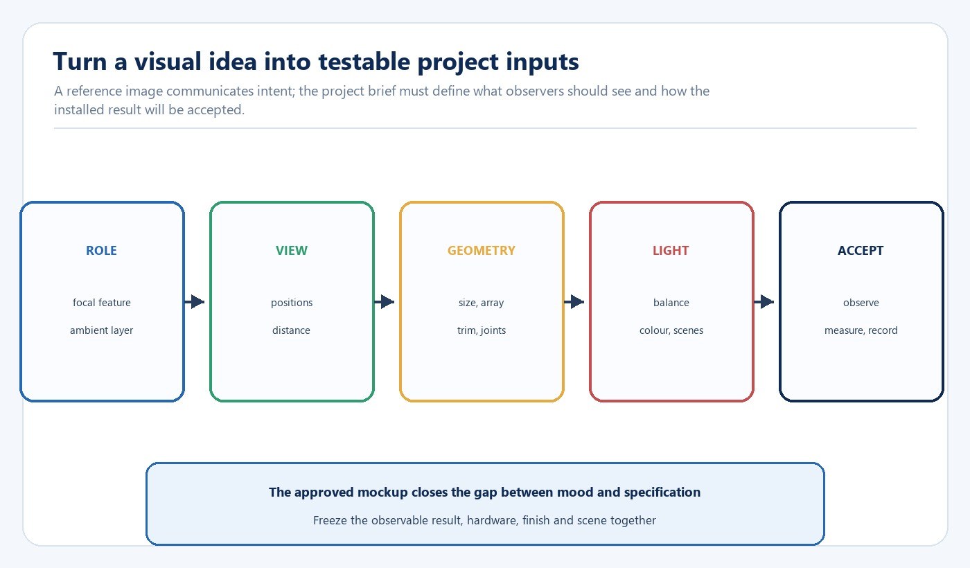
Begin with the room and the observer. Record where people enter, sit, stand and circulate; the distances and angles from which the luminous plane will be seen; and whether it should read as a focal feature, a depth-like ceiling element or a softer ambient layer. Reference images can communicate mood, but the project needs a description that can be checked in the installed space.
Write the brightness relationship rather than asking for a panel that simply looks “bright.” State how the artificial skylight should relate to the ceiling, walls, task areas and adjacent luminaires in each scene. Include colour appearance, transitions and the visual priority of trim lines and joints.
| Decision | Project input | Mockup check | Release record |
|---|---|---|---|
| Visual role | Focal plane, ambient layer or both | Key viewpoints and room scenes | Accepted photographs and observations |
| Geometry | Module, array, trim, joint and ceiling datum | Alignment, proportions and visible gaps | Drawings and finish sample |
| Light | Output, distribution, colour and dimming | Luminance balance, glare and transitions | Scene settings and measurements |
| Integration | Support, cavity, power and access | Installation sequence and service route | Coordination drawing |
| Controls | Schedule, local override and interfaces | Commands, recovery and handover | Commissioning file |
The Artificial Skylight & Daylight solution provides the application context. For a modular ceiling layout, the P Series artificial skylight can be reviewed alongside the room grid and array geometry; recessed projects can compare the D Series artificial skylight with the proposed opening and trim condition.
Separate Electric Lighting, Daylight and Integrative-Lighting Objectives
ISO/CIE 8995-1:2025 addresses the quantity and quality of illumination in indoor workplaces and allows lighting solutions to use daylight, electric light or a combination. An artificial skylight belongs to the electric-light part of that design. If a project has daylight targets, calculate them from the actual building openings and the applicable daylight method.
Keep visual appearance and biological objectives in separate lines of the brief. ISO/CIE TR 21783:2022 explains that ipRGC-influenced responses depend on the spectrum, intensity, duration and timing of light exposure. A blue-sky appearance or a high correlated colour temperature does not by itself define a complete exposure pattern.
For workplace projects, determine the relevant task illuminance, glare, colour quality and visual-comfort requirements for the actual space. If the client also has an integrative-lighting objective, define the exposure schedule, measurement basis and affected population with qualified design input. This keeps the artificial-skylight feature useful without asking its appearance to carry claims that depend on the whole environment and daily exposure.
Review the Product as a System, Not a Flat Image
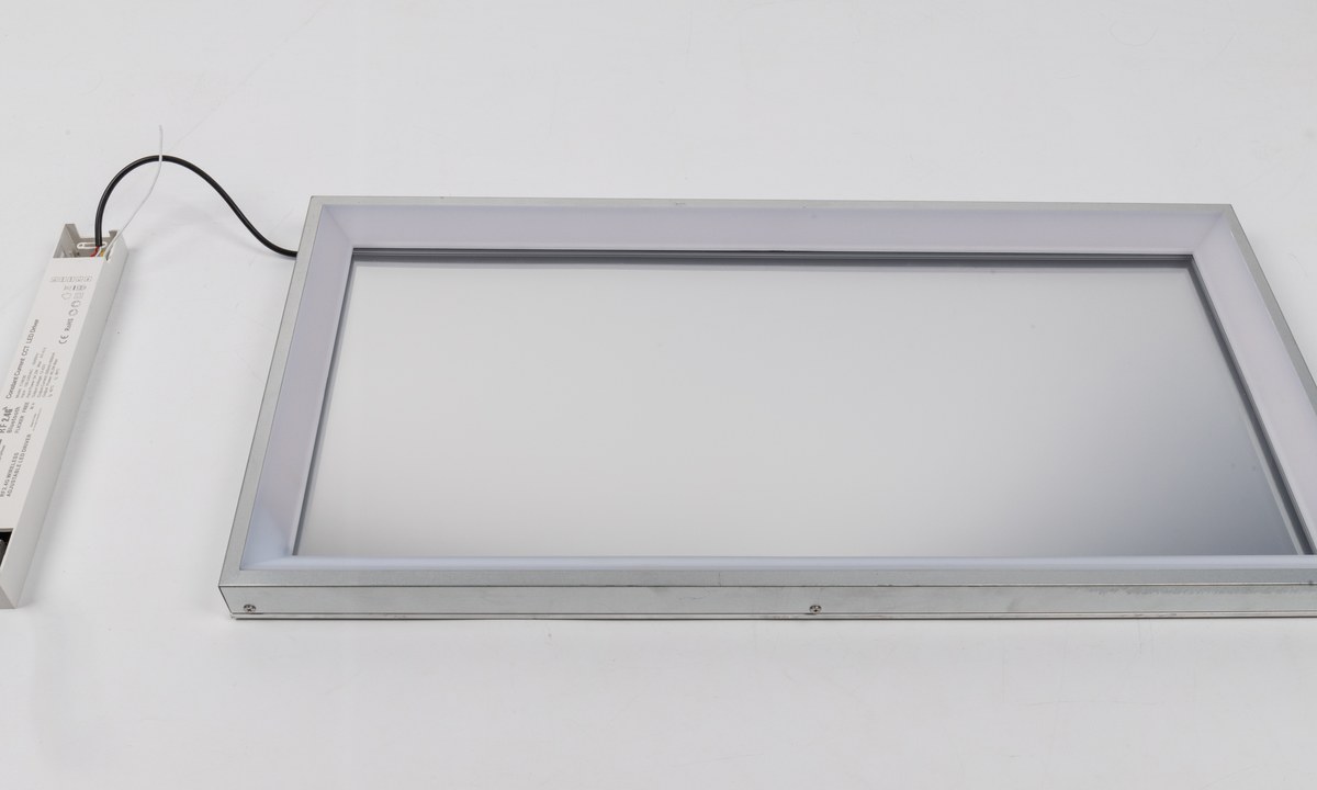
The visible plane is only one part of the system. The module, frame, diffuser or optical layers, driver, cables, connectors and controls all need a place in the ceiling design. Record which components are supplied with the product and which are provided by the installer or control contractor.
Confirm the exact module dimensions, depth, weight, input, driver location, control method and access requirements from the selected product documentation. Do not infer project dimensions from a presentation image. An external driver may allow a thin visible frame while increasing the coordination needed for mounting, cable reach, ventilation and service clearance.
The product arrangement also affects the visual result. A single module, repeated grid and custom array create different joint patterns and proportions. Decide whether trims should be visible, aligned with the ceiling grid or concealed within a continuous opening. Lock that geometry before the ceiling contractor releases framing.
Coordinate the Ceiling, Structure and Services
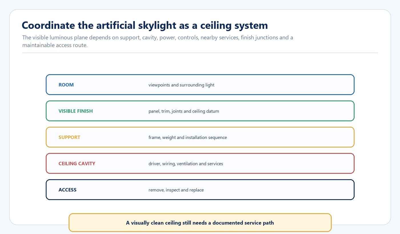
Issue reflected ceiling plans and sections that show the module or array, opening, trim, support points, ceiling datum and surrounding finishes. Add cavity depth, structural zones, ducts, pipes, sprinklers, cable trays, drivers, control devices and access panels. A plan view alone cannot confirm that the equipment fits above the visible ceiling.
Assign each interface. The lighting supplier should define the product envelope and required connections; the architect or interior designer should control the visible opening and finish; structural and ceiling trades should confirm support; the electrical and controls teams should coordinate power, protection, control wiring and commissioning; the main contractor should coordinate sequence and access.
| Interface | Information required before release | Responsible evidence |
|---|---|---|
| Opening and trim | Finished dimensions, tolerance and joint detail | Coordinated reflected ceiling plan and section |
| Support | Product weight, support points and ceiling system capacity | Approved support detail |
| Power and driver | Supply, circuit, location, cable reach and ventilation | Electrical drawing and product schedule |
| Controls | Interface, scenes, sensor logic, override and recovery | Control narrative and device schedule |
| Maintenance | Removal direction, access route and replacement clearance | Service demonstration in the mockup |
Service access is a design input, not a handover afterthought. A driver or connector placed behind a sealed finish can turn a replaceable component into disruptive ceiling work. Demonstrate how the module, trim and service parts can be reached without damaging adjacent finishes.
Evaluate the Illuminated Plane in the Complete Room

Judge the feature with the surrounding lighting and finishes operating. A bright ceiling panel can be visually striking while leaving faces, walls or tasks underlit. It can also dominate the field of view when the surrounding ceiling and vertical surfaces are much darker. Review luminance balance and glare from the real seated and standing positions.
Include task lighting, vertical illumination, accents, circulation and emergency lighting in the room plan. Check reflections on screens, glass and polished surfaces. Large luminous planes can appear different from oblique angles, so examine the array from entrances and side views rather than only from directly below.
CIE 222:2017 presents a user-requirement-based decision scheme for lighting controls in non-residential buildings. Translate that principle into the project control narrative: identify schedules, occupancy or daylight responses, scene transitions, local override, integration ownership and the state after power returns. The LED driver, dimming and control compatibility guide provides a representative circuit test method for the selected hardware.
Build and Approve a Representative Mockup
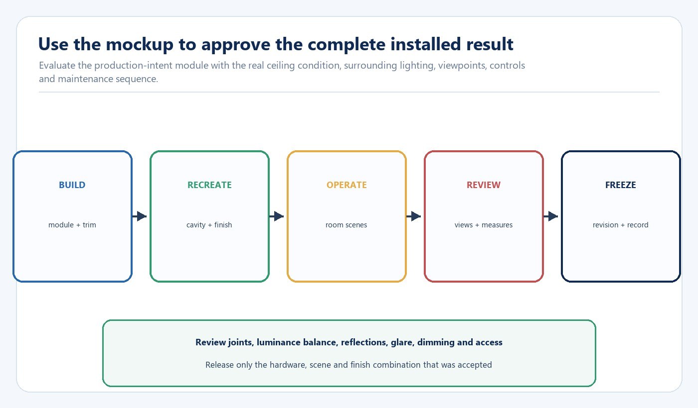
Use a production-intent module, trim, driver and control interface. Reproduce the proposed cavity, ceiling finish, joint, viewing distance and surrounding surfaces. Operate the other room lighting so the reviewer sees the intended luminance balance rather than an isolated panel in a dark test area.
Review the mockup from the documented viewpoints and scenes. Observe joints, hotspots, colour consistency, reflections, glare, low-level dimming and transitions. Measure the agreed criteria at defined positions. Then open the service route, remove or access the relevant components and restore operation.
Record the accepted product identity, hardware and firmware where applicable, array geometry, trim and finish, scene settings, observations, measurements and approval date. The LED lighting sample evaluation checklist can control sample identity and evidence before the project mockup is signed off.
Control Installation, Commissioning and Handover
Plan the handling route and installation sequence for each module. Confirm when support, power, controls and ceiling finishes are available; which trade makes each connection; and how protective films or optical surfaces remain clean. Qualified personnel should complete electrical installation under the applicable project rules.
Commission every scene and control path represented in the brief. Test local commands, schedules, sensors, integrations, low and full output, power interruption and recovery. Save the final settings and device schedule, and identify who can change them after handover.
The handover package should include product documents, as-built locations, driver and control identities, access instructions, commissioning files, approved scene values and spare-parts decisions. Send the ceiling plan, sections, viewpoints, required scenes and mockup criteria through the New Lights project enquiry form for project review.
Project Release Checklist
- The feature is defined as an electric luminous ceiling system.
- Room, users, viewpoints, visual role and acceptance criteria are written.
- Module, array, trim, joints and ceiling datum are coordinated.
- Support, cavity, power, controls, nearby services and access are assigned.
- Task, vertical, circulation, accent and emergency lighting are included.
- Daylight and integrative-lighting objectives use their own metrics and evidence.
- A production-intent mockup is reviewed in representative room conditions.
- Hardware, finish, scene and commissioning records are frozen together.
Frequently Asked Questions
Does an artificial skylight count as daylight?
No. It is electric lighting. Daylight calculations should use actual building openings and the applicable daylight method.
Can one artificial-skylight panel replace all other room lighting?
Do not assume so. The room still needs appropriate task, vertical, circulation, accent and emergency lighting, with glare and luminance balance checked from real viewpoints.
What should the mockup reproduce?
Use the production-intent module, trim, driver and controls with representative ceiling depth, finish, joint, viewing distance, room surfaces and surrounding lighting scenes.
What must be accessible after installation?
Provide a practical route to the driver, connectors, control components and removable module or trim parts identified in the product and project service plan.
Editorial Sources
- CIE, “Light and lighting — Lighting of work places — Part 1: Indoor,” ISO/CIE 8995-1:2025(en): https://cie.co.at/publications/light-and-lighting-lighting-work-places-part-1-indoor-0
- CIE, “Light and lighting — Integrative lighting — Non-visual effects,” ISO/CIE TR 21783:2022(E): https://www.cie.co.at/publications/light-and-lighting-integrative-lighting-non-visual-effects
- CIE, “Decision Scheme for Lighting Controls in Non-Residential Buildings,” CIE 222:2017: https://www.cie.co.at/publications/decision-scheme-lighting-controls-non-residential-buildings












