


A high-CRI dimmable LED spotlight is not automatically flicker-free. Color rendition, temporal light modulation (TLM), and dimming compatibility are separate performance dimensions. A project needs evidence for each one, followed by a mockup of the exact lamp, dimmer, load, fixture, voltage, and scene settings.
This distinction changes the buying process. Instead of accepting three labels on a specification sheet, define the visual task, request model-level color and TLM data, verify the control architecture, and test behavior across the usable dimming range. The result is a repeatable acceptance decision rather than a promise that may fail after installation.
Start With the Decision, Not the CRI Number
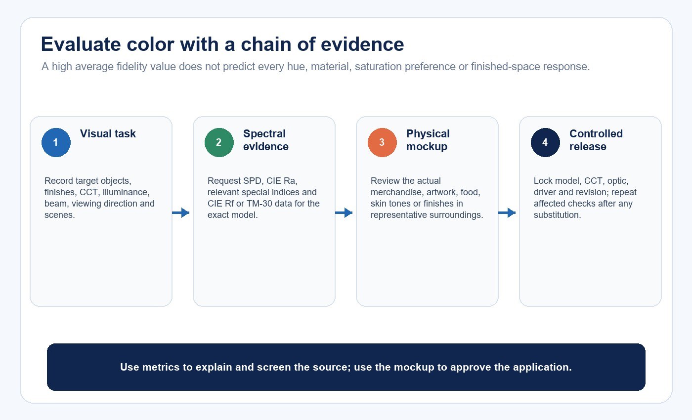
Begin by describing what the spotlight must reveal. Retail merchandise, food, artwork, skin tones, timber, textiles, and metallic finishes do not create the same color-rendering priorities. Record the target objects, surrounding surfaces, illuminance, correlated color temperature (CCT), beam size, viewing direction, adaptation conditions, and the scenes users will actually select.
Then define the control outcome. A restaurant may need a smooth transition to a very low evening scene. A retail display may need stable color and consistent output between adjacent fittings. A residence may place higher value on silent operation and predictable wall-dimmer behavior. These are acceptance criteria, not interchangeable versions of “dimmable.”
Use the color temperature and CRI application guide to establish the wider visual brief before narrowing the decision to a spotlight and control combination.
| Requirement | Question to answer | Evidence to request | Where to verify |
|---|---|---|---|
| Color rendition | Which objects and hues must look acceptable? | SPD, CIE Ra, relevant special indices, TM-30 or CIE Rf data | Report plus physical mockup |
| TLM | Which visual effects and operating levels matter? | Waveform, frequency, modulation and project-selected metrics | Full output and dimmed checkpoints |
| Dimming | What minimum level and transition quality are required? | Control method, compatibility list, load range and curve | Exact lamp-dimmer-load circuit |
| Optical result | Does the beam put light where it is needed? | Beam data, photometric file and fixture information | Installed or representative geometry |
Treat Color Rendition as a Set of Evidence
CIE Ra remains common, but it is an average fidelity metric. It cannot by itself describe every hue shift, saturation change, preference, discrimination task, or the way real materials look in a finished space. A high value is useful only when the metric, test conditions, exact CCT, model, optic, and application are known.
The U.S. Department of Energy describes ANSI/IES TM-30-24 as a system of related measures and graphics for evaluating and communicating color rendition. Its measures can add average fidelity, average gamut, and hue-specific information to a specification. The CIE’s 2025 position statement also recommends beginning to adopt CIE Rf and reporting it in parallel with CIE Ra during the transition, while noting that complete color quality needs more than fidelity alone.
Ask for the spectral power distribution (SPD) and the measurement conditions behind the reported values. Two spotlights with similar CIE Ra can distribute spectral energy differently and render particular materials differently. That is why the final check belongs in a mockup using the actual merchandise, artwork, fabrics, food, or finishes.
Define Flicker and TLM Before Setting a Limit
“Flicker-free” is too vague for a procurement decision. TLM can produce direct flicker, stroboscopic effects, or phantom-array effects, and different metrics describe different portions of that behavior. A usable requirement identifies the measurement method, metric, limit, waveform conditions, frequency range, dimming level, and application.
DOE’s solid-state-lighting resources list standards and methods including IES LM-90 for measuring luminous-flux waveforms and CIE 249 for visual aspects of time-modulated lighting systems. The important practical point is that one number does not characterize every waveform, operating state, observer, camera, or moving task.
Measure the exact product at full output and at multiple points through the usable dimming range. Include startup, steady state, slow transitions, rapid scene changes, warm operation, cold start when relevant, and supply conditions expected on site. A lamp may look stable at 100% and become unstable near the low end because the driver and dimmer interact differently there.
For a broader electrical review, the LED flicker, power factor and THD buyer checklist explains why these metrics must be evaluated separately rather than substituted for one another.
Map the Complete Dimming Chain
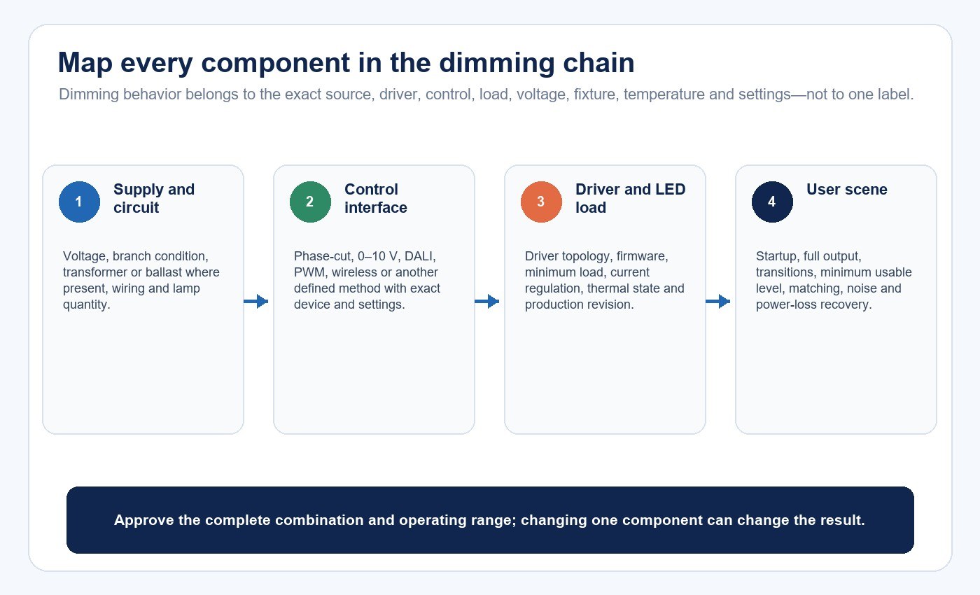
Dimming is a system behavior. The chain may include the utility supply, branch circuit, wall control or building-control system, transformer or ballast where present, lamp driver, LED load, firmware, thermal condition, fixture, and number of lamps on the circuit. Changing one item can change startup, minimum level, noise, light stability, or the curve.
Identify the control method before comparing products. Phase-cut replacement lamps, 0–10 V luminaires, DALI systems, PWM-controlled drivers, and wireless controls do not have the same interfaces or failure modes. A “dimmable” statement without the control method and tested configuration leaves the most important compatibility question unanswered.
DOE’s phase-cut dimming guidance notes that compatibility between a specific LED source and a specific dimmer can be difficult to predict, and that compatibility alone does not guarantee smoothness, lack of flicker, or a particular minimum dimmed level. The LED driver, dimming and control compatibility guide provides the broader system-selection workflow.
Specify the Usable Dimming Range
A minimum dimming claim needs a reference. “Dims to 5%” could refer to control command, input power, measured light output, or perceived brightness. Those values are not necessarily equal. Define what is measured, at which point, with what instrument, and using which exact lamp, dimmer, load, and voltage.
Check more than the lowest stable point. The curve should be monotonic and usable from the user’s perspective. Record pop-on, dropout, dead travel, shimmer, flashing, hunting, audible noise, multi-lamp matching, restart behavior, and whether a power interruption restores the intended scene.
| Checkpoint | Record | Typical failure signal | Decision implication |
|---|---|---|---|
| Cold start at low command | Start success, delay and initial output | No start, flash or jump to high output | Combination is not acceptable for that scene |
| Full output | Light output, power, TLM and noise | Reduced output, modulation or buzz | Verify loading and control mode |
| Mid-range transition | Output curve and lamp matching | Steps, hunting or unequal lamps | Review dimmer, driver and quantity |
| Minimum usable level | Stable output, waveform and color | Dropout, shimmer or color shift | Raise approved low-end or change system |
| Warm restart | Recovery after thermal stabilization | Different low-end or delayed start | Add thermal condition to acceptance |
Verify Beam, Glare and Fixture Conditions
A spotlight can meet color and TLM targets yet fail the application because of beam geometry or glare. Confirm beam angle, field angle, center intensity, spill, cutoff, aiming range, luminous-aperture brightness, and the relationship between the fixture and target.
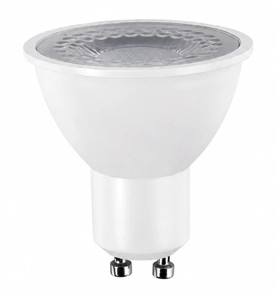
For replacement lamps, the host fixture affects distribution, temperature, shielding, and sometimes electrical conditions. Confirm base, physical envelope, center-beam alignment, enclosure restrictions, ventilation, and dimmer interface. The published New Lights GU10 LED spot-bulb range can be used to identify a product family for a project review, but color, dimming, TLM, lifetime, and certification claims must still be tied to the exact requested model and its supporting documents.
Build a Representative Mockup
The mockup should reproduce the difficult parts of the intended installation, not only a convenient bench condition. Use the exact spotlight, production revision, fixture, voltage, dimmer or controller, lamp quantity, wiring arrangement, trims, room surfaces, target objects, and scene levels.
Test after thermal stabilization and also during startup conditions relevant to the site. Review color appearance, beam placement, glare, TLM, minimum level, smoothness, matching between lamps, audible noise, power, temperatures, and recovery after power loss. Include cameras or moving objects when the application makes temporal artifacts especially visible.
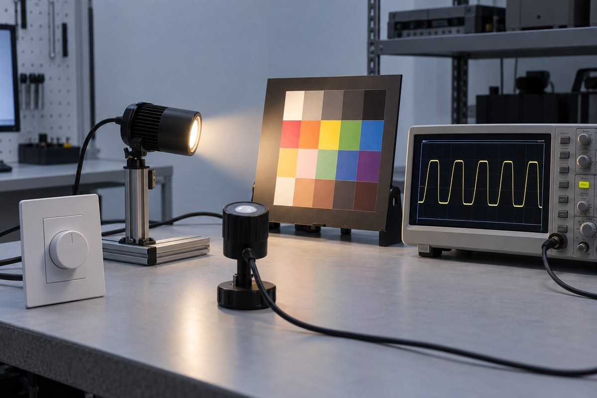
Record instrument identifiers, settings, waveform files, measurements, photographs, reviewer decisions, and every component revision. The approval should identify a locked combination that purchasing and installation teams can reproduce.
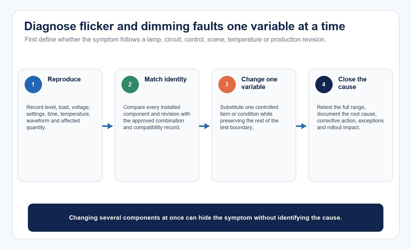
Diagnose Problems One Variable at a Time
When a complaint appears, first define its boundary. Does it affect one lamp, one circuit, one dimmer type, one scene, one temperature state, or the whole site? Record the operating level, load quantity, voltage, control settings, timing, ambient conditions, and whether products or revisions are mixed.
Compare installed components with the approved combination and compatibility information. Qualified personnel can then check for incorrect loading, incompatible control mode, loose connections, supply disturbance, transformer or ballast interaction, overheating, mixed revisions, or unauthorized substitutions. Do not bypass protective devices or improvise wiring to force stable operation.
Change one controlled variable per test. Replacing several components at once may remove the symptom without identifying the cause, making the same problem likely to recur elsewhere.
Use a Model-Level Procurement Matrix
Create one row for each exact model, CCT, optic, driver, base, and dimming option. A family brochure may not cover every combination, and a test report for one revision does not automatically prove another.
| Evidence field | Minimum identification | Acceptance question |
|---|---|---|
| Color | SPD, CIE Ra, CIE Rf or TM-30 data, CCT and test condition | Does the exact sample meet the visual brief? |
| TLM | Waveform, method, metric, frequency and dimming checkpoints | Are agreed limits met throughout the usable range? |
| Dimming | Control method, dimmer models, voltage, load and lamp quantity | Is the exact system compatible and usable? |
| Optical | Photometry, beam/field angles, optic and host fixture | Does the installed geometry light the target without unacceptable glare? |
| Electrical and thermal | Input data, power quality, ambient and enclosure limits | Is the evidence valid for the intended installation? |
| Governance | Revision, sample record, change control and unresolved items | Can the approved combination be reproduced in production? |
For commercial display projects, the Commercial & Retail Lighting Solutions page provides application context. Buyers who need production and change-control evidence can also review New Lights factory and manufacturing capabilities.
Decide What to Approve
Approve a spotlight system only when the evidence chain closes: requirement, model identity, test method, result, operating conditions, mockup decision, and controlled production configuration. If one stream remains unresolved, record it rather than allowing a broad label to stand in for evidence.
This approach also keeps the three decisions separate. A product may meet the color goal but fail the low-end control requirement. It may dim smoothly but not meet the project’s TLM criterion. It may pass the bench test yet create glare or poor beam placement in the real fixture. The correct response is to change the failed part of the system or adjust the approved operating boundary—not to assume the remaining claims compensate for it.
To review a specific combination, contact New Lights with the application, target objects, exact lamp and fixture, dimmer or controller, circuit load, voltage, color metrics, minimum level, TLM criteria, market, and sample-test plan.
Frequently Asked Questions
Does high CRI guarantee attractive or accurate color?
No. CIE Ra is an average fidelity metric. Spectrum, specific hues, gamut, preference, illuminance, CCT, objects, surrounding colors, and adaptation all influence the visual result.
Does dimmable mean flicker-free?
No. Dimming compatibility and TLM performance depend on the exact source, driver, dimmer, load, voltage, settings, temperature, and operating level.
What should replace an undefined flicker-free claim?
Specify the waveform measurement method, selected metrics, limits, operating conditions, dimming checkpoints, exact sample configuration, and acceptance record.
Why can a spotlight flicker only near minimum output?
Possible causes include dimmer minimum-load behavior, driver-control interaction, low-end trim, supply variation, component tolerance, thermal state, mixed loads, or an incompatible control method.
Is TM-30 a replacement for a physical mockup?
No. TM-30 provides richer color-rendition information, but the project must still review the actual objects, beam, glare, illuminance, dimming scenes, and observer response.
What is the most useful compatibility test?
Test the exact installed combination through cold start, full output, multiple dimming levels, slow and rapid transitions, thermal stabilization, power interruption, multi-lamp loading, and normal user controls.
Editorial Sources
- U.S. Department of Energy, “TM-30 Frequently Asked Questions”: https://www.energy.gov/cmei/ssl/tm-30-frequently-asked-questions
- International Commission on Illumination, “CIE PS 002:2025 — CIE Position Statement on Colour Quality Metrics, 2nd Edition”: https://www.cie.co.at/publications/cie-ps-0022025-cie-position-statement-colour-quality-metrics-2nd-edition
- U.S. Department of Energy, “Metrics and Test Methods”: https://www.energy.gov/cmei/ssl/metrics-and-test-methods
- U.S. Department of Energy, “Dimming LEDs with Phase-Cut Dimmers: The Specifier’s Process for Maximizing Success”: https://betterbuildingssolutioncenter.energy.gov/sites/default/files/attachments/2013_gateway_dimming.pdf












