


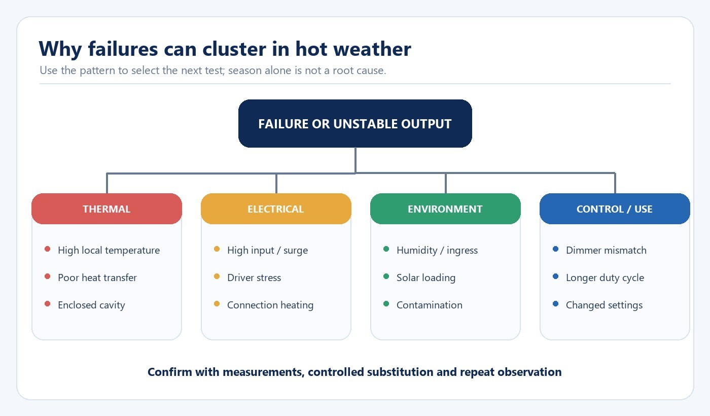
LED failures that appear more often in summer usually indicate that an existing margin has narrowed. Higher ambient temperature may be part of the cause, but solar loading, enclosed fixtures, ceiling cavities, longer operating hours, unstable supply conditions, moisture and driver stress can produce a similar seasonal pattern. The useful question is therefore not simply whether the weather was hot. It is which component exceeded its intended operating condition, where that condition occurred and what evidence separates thermal stress from another failure mode.
The fastest reliable investigation defines the exact product and installation, records the failure pattern, measures the relevant temperatures and electrical conditions, isolates one domain at a time and then repeats the original test after correction.
Start with the complete thermal path
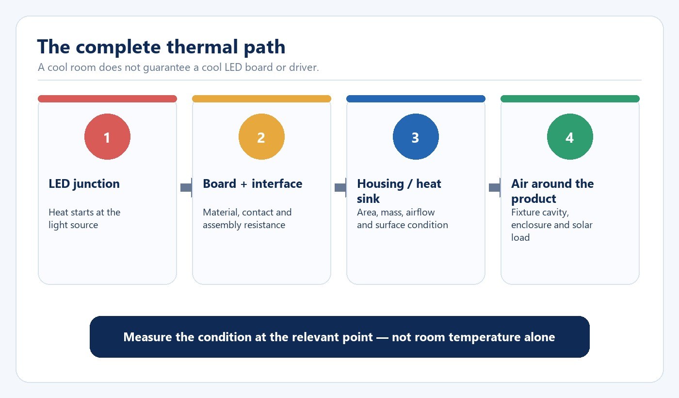
An LED system moves heat through several interfaces: from the LED junction into the board, through interface materials and mechanical joints, into the housing or heat sink, and finally to the surrounding air. A driver creates its own heat and may share the same enclosure. Any weak interface can raise component temperature even when the room feels comfortable.
The U.S. Department of Energy (DOE) describes product temperature as a function of power dissipation, thermal resistance and ambient temperature. This is why room temperature alone is not enough. The air trapped above a ceiling, inside a sealed decorative fitting or behind an insulated surface can be considerably different from the occupied space below it.
| Layer to check | Evidence to collect | Decision it supports |
|---|---|---|
| Application environment | Expected ambient range, solar exposure, ceiling-cavity condition and ventilation | Whether the installation stays within the product’s declared range |
| Installed product | Exact model, wattage, driver, revision, mounting and enclosure | Whether the tested evidence represents the field configuration |
| Relevant temperature point | Manufacturer-defined case or measurement point, stabilization time and method | Whether the installed thermal condition matches the approved basis |
| Electrical input | Voltage, frequency, switching events, surge environment and control state | Whether electrical stress is being mistaken for a thermal failure |
| Failure outcome | No light, cycling, reduced output, color shift, discoloration or intermittent operation | Which component and test path should be prioritized |
For a product-specific example of how housing material, cavity temperature and measurement points interact, see the full-plastic LED downlight thermal-management guide.
Define what “failure” means before diagnosing it
Complete loss of light is only one outcome. A hot-condition complaint may be intermittent cycling after warm-up, reduced output caused by thermal protection, visible color change, unstable dimming, driver noise, discoloration or accelerated lumen loss. These outcomes do not all point to the LED package.
DOE notes that catastrophic luminaire failure is often associated with electronics, while useful-life concerns can also include lumen depreciation and unacceptable color shift. A system-level investigation should therefore identify the symptom and the component boundary before making a replacement decision.
| Observed pattern | First domains to inspect | Useful comparison |
|---|---|---|
| Unit turns off and restarts after warm-up | Thermal protection, driver, airflow and load | Cold start versus thermally stabilized operation |
| Several units fail together | Supply event, control command, common enclosure or environmental exposure | Affected circuit versus unaffected circuit |
| One unit repeatedly fails in one location | Local cavity, insulation contact, water path, connector or unit defect | Same unit in approved reference location; known-good unit in suspect location |
| Output or color drifts without shutdown | LED package, optics, temperature history and operating hours | Initial data, retained sample and current measurement |
| Failure follows storms or switching events | Surge protection, earthing, supply transient and driver input stage | Event records and circuit-level inspection |
If the priority is to separate supply, driver and LED-board faults, use the broader LED light failure diagnosis workflow. The present guide owns the thermal and hot-weather branch of that decision.
Why summer can expose a marginal system
Higher outdoor temperature reduces the difference between the product surface and its surroundings, so heat rejection becomes more difficult. Direct sun can add a second load. A roof space may remain hot after the occupied room cools, and an enclosed fixture can retain heat around both the light source and the driver. Longer evening use can also extend the stabilized operating period.
At the same time, summer may bring thunderstorms, voltage events and humidity. A failure cluster that happens in the same season is therefore evidence about timing, not proof of a thermal root cause. The diagnostic plan must keep the main domains separate.
For exposed luminaires, the outdoor LED wall-light failure guide covers ingress paths, sealing, mounting and site exposure in more detail. For roadway projects, the streetlight driver reliability guide addresses input protection and driver-level evidence.
Measure conditions at the relevant point
The measurement plan should come from the product or system design. Record ambient temperature at a defined location, the relevant case or housing point, input voltage, power, operating mode and stabilization time. Photograph the installed geometry so that insulation, enclosure, nearby heat sources and airflow restrictions are visible.
Do not place a sensor on an arbitrary convenient surface and treat it as junction temperature. Do not compare a laboratory value with a field measurement taken at a different point. Where the manufacturer defines a Tc or another reference location, use that point and method. Junction temperature may require calculation or a validated relationship rather than direct field measurement.
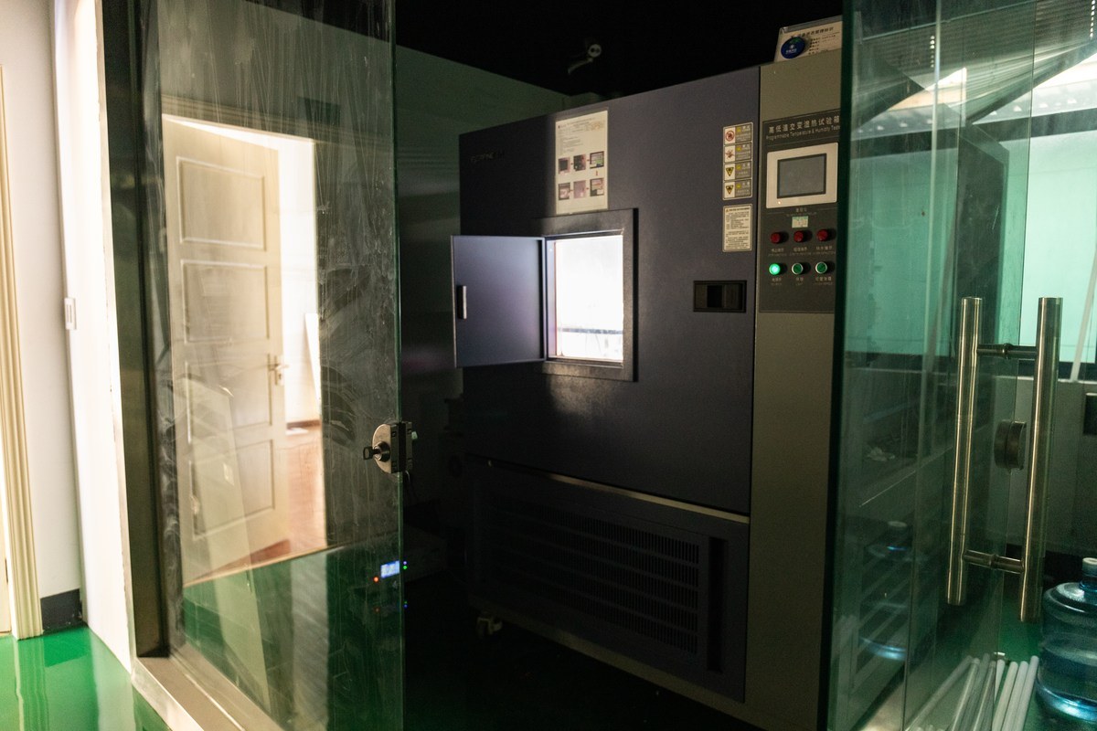
The test condition must represent the actual configuration. A bare lamp on an open bench cannot establish performance inside a closed decorative fitting. A driver tested outside the luminaire may run cooler than it does in production. A reduced-wattage sample does not represent a higher-power model unless the thermal design and evidence explicitly connect them.
Separate package data from complete-product reliability
LED package lumen-maintenance data answer a narrower question than complete-product lifetime. LM-80 data characterize LED package, array or module lumen maintenance under defined conditions; TM-21 is used to project long-term maintenance from that data. Those records do not include every driver, connector, seal, solder joint, optic and enclosure failure mode in the installed product.
For a complete luminaire or lamp, ask how package data, measured product temperatures, driver ratings, protection design and system-level tests connect. The evidence chain should identify the exact model or family boundary and the conditions under which the conclusion applies.
| Evidence | What it can support | What it cannot establish alone |
|---|---|---|
| LED package LM-80 data | Package-level lumen and chromaticity maintenance under test conditions | Complete luminaire or driver lifetime |
| TM-21 projection | A projection derived from eligible package data | Field performance outside the represented temperature/current conditions |
| Product thermal measurement | Temperature at the defined point in the tested configuration | Every installation, enclosure or ambient condition |
| Driver component/rating data | Suitability of the selected driver and components for declared conditions | Installed system reliability without thermal and electrical context |
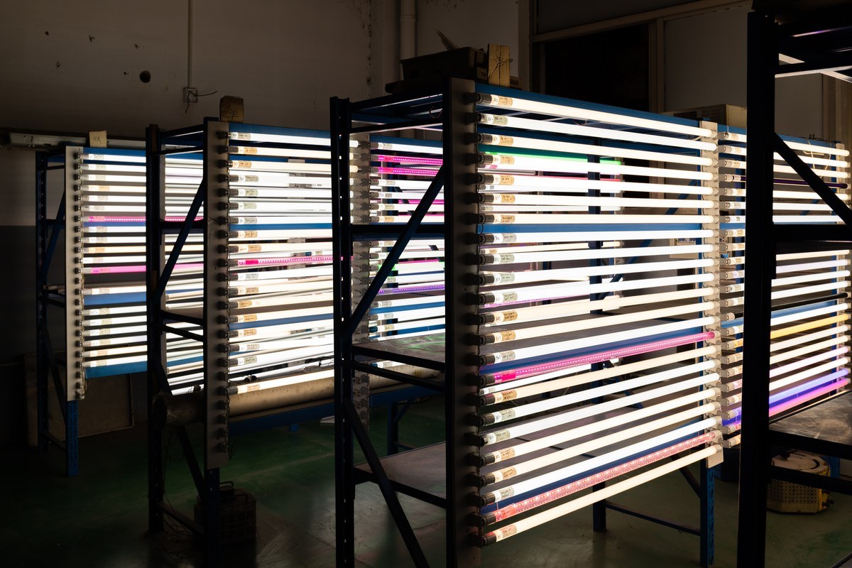
| Aging or stress test | Behavior of identified samples under a documented test plan | A universal life claim for unrelated models or conditions |
Build a controlled field investigation
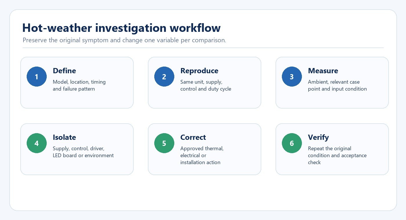
Start with the smallest comparison that can separate location, product and supply. Preserve failed units where practical; a discarded driver or connector can remove the evidence needed to distinguish overheating from a transient or assembly issue.
- Record the exact model, revision, driver, control and installation geometry.
- Map affected and unaffected units by circuit, location, batch and operating schedule.
- Reproduce the symptom without changing several variables at once.
- Measure the defined thermal and electrical conditions through warm-up and steady operation.
- Use an approved known-good comparison to isolate location, supply or unit-level effects.
- Apply the corrective action, then repeat the original condition and acceptance check.
Line-voltage measurements, internal inspection and component substitution require qualified personnel and the approved service procedure. Do not bypass thermal protection, surge protection or safety devices to keep a unit operating.
Choose corrective action from the confirmed boundary
If the installed thermal condition exceeds the product’s declared range, the correction may involve a more suitable product, lower power, improved heat transfer, a different mounting arrangement, added clearance or a fixture intended for the enclosure. If the driver is the limiting component, component derating, driver placement or a different driver architecture may be relevant—but these are design decisions, not field improvisations.
If the failure follows voltage events, focus on the supply and protection chain. If it follows water paths or condensation, correct the environmental boundary and sealing details. If it follows a dimmer or control state, retest the exact control combination. Replacing the LED board alone will not correct a recurring system condition.
What buyers should request before approval
- Declared operating ambient range for the exact product.
- Product drawing showing the relevant thermal measurement point where applicable.
- Thermal test configuration, stabilization criteria and results tied to model identity.
- Driver make, model, critical component ratings and protection architecture.
- LED package lumen-maintenance evidence and the conditions used for any projection.
- Enclosed, insulated, outdoor or high-bay installation restrictions.
- Change-control rules for driver, LED board, interface material, housing and firmware.
- Failure-analysis process and retained-sample plan for pilot and production lots.
For a project-specific review, contact New Lights with the model list, installation photographs, ambient range, operating schedule, driver/control identity and any failed samples or measurement records.
Frequently Asked Questions
Does hot weather directly damage every LED light?
No. Hot weather reduces thermal margin, but the installed product, local air temperature, solar exposure, enclosure, power, driver and duty cycle determine whether a limit is exceeded.
Is room temperature enough for a thermal check?
No. The relevant local ambient, product measurement point, installation geometry and stabilized operating condition are needed.
Does LM-80 prove the complete lamp or luminaire lifetime?
No. It supports package-level lumen-maintenance evaluation under specified conditions; the driver and other system components require separate evidence.
Why does an LED light cycle on and off after warming up?
Thermal protection or an unstable driver can create cycling, but supply and control conditions can look similar. Reproduce the timing and measure before replacing parts.
Can a higher-rated driver solve a summer failure?
Not automatically. Electrical compatibility, output current, protection behavior, thermal location, enclosure and approvals must match the product design.
What is the best first comparison in the field?
Compare affected and unaffected units while holding as many variables constant as possible, then change one approved variable at a time.
Editorial Sources
- U.S. Department of Energy, LED Basics
- U.S. Department of Energy, LED Luminaire Lifetime: Recommendations for Testing and Reporting
- U.S. Department of Energy, LED Systems Reliability Consortium
- U.S. Department of Energy, LED Luminaire Reliability: Impact of Color Shift
- Illuminating Engineering Society, ANSI/IES LM-80
- Illuminating Engineering Society, ANSI/IES TM-21












