Phase-cut dimming changes LED light output by removing part of each alternating-current half-cycle before the waveform reaches the driver. The two main forms are forward-phase, also called leading-edge, and reverse-phase, also called trailing-edge. Adaptive or phase-selectable controls can choose between those modes, but they do not remove the need to verify the exact LED driver and load.
The common shortcut—“use trailing-edge for LED”—is not a dependable specification rule. Some LED drivers are designed for reverse-phase, some for forward-phase, and some accept both only within stated limits. Dimming quality also depends on the dimmer, number of drivers, input circuit, inrush current, leakage, trim settings and firmware or product revision.
The LED driver, dimming and control compatibility guide covers the wider control-system boundary. This article concentrates on phase-cut selection and commissioning.
What Phase-Cut Dimming Actually Changes
An AC line waveform crosses zero and rises and falls during each half-cycle. A phase-control dimmer delays or ends conduction during part of that half-cycle. The LED driver must interpret the resulting chopped waveform while maintaining stable output to the LED load.
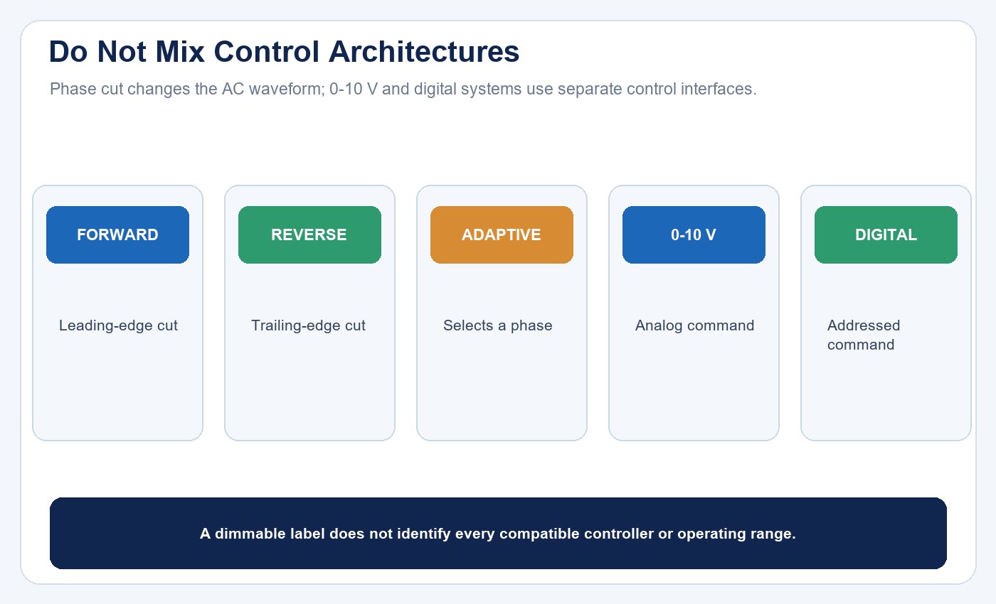
This is different from a separate low-voltage or digital control signal. A 0–10V system commonly supplies continuous power to the driver and sends a separate analog control signal. DALI, DMX and proprietary digital systems communicate commands through their own interfaces. They may be alternative control architectures, but they are not additional varieties of leading-edge or trailing-edge waveform cutting.
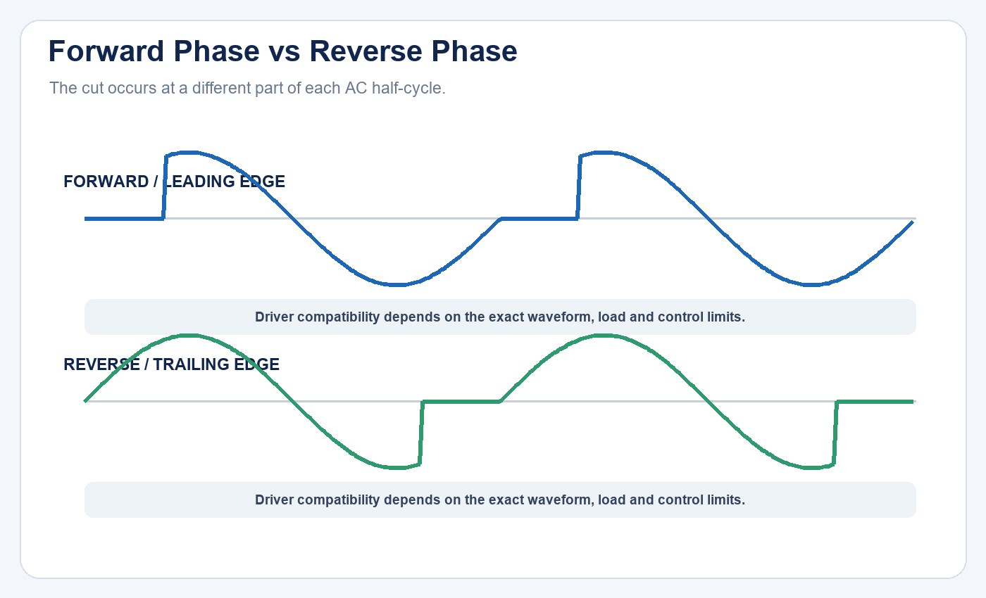
Forward phase removes the beginning of each half-cycle; reverse phase removes the end. Waveform terminology alone does not establish compatibility.
| Control method | What changes | Separate control conductors | Compatibility decision |
|---|---|---|---|
| Forward phase | Beginning of each AC half-cycle is removed | Commonly no | Exact dimmer-driver-load combination |
| Reverse phase | End of each AC half-cycle is removed | Commonly no | Exact dimmer-driver-load combination |
| Adaptive phase | Control selects or detects a phase mode | Product dependent | Selected mode and load must be recorded |
| 0–10V or digital | Separate analog or digital command | Usually yes | Protocol, roles, wiring and commissioning |
Forward-Phase or Leading-Edge Control
Forward-phase control removes the beginning of each AC half-cycle and turns conduction on after a delay. It has a long history with incandescent loads and magnetic low-voltage transformers, and many phase-dimmable LED products are also designed to use it.
The label does not guarantee a particular dimming range or behavior. An LED driver connected to an unsuitable forward-phase control may flicker, turn on late, drop out at the low end, produce audible noise or fail to turn fully off. The dimmer may also need a minimum load or neutral connection, depending on its design.
Forward-phase can be the correct mode when the driver manufacturer specifies it or when a tested compatibility report confirms the combination. It should not be rejected simply because the load is LED. Equally, a legacy forward-phase wall dimmer should not be retained automatically just because it appears to change brightness.
Use the TLED driver power supply selection guide to verify the driver input, output, thermal and protection boundaries before evaluating its control behavior.
Reverse-Phase or Trailing-Edge Control
Reverse-phase control begins conduction near the start of each half-cycle and turns it off before the half-cycle ends. It is often associated with electronic low-voltage loads and many modern LED drivers. The switching behavior can suit some electronic inputs better than forward-phase control, but “often” is not the same as “always.”
Some drivers require forward-phase, some accept reverse-phase, and some list different performance limits for each. A reverse-phase control also has its own load rating, device-count, thermal and wiring requirements. Do not convert a manufacturer preference into a universal industry rule.
When reverse-phase is supported, confirm the tested control model, supply voltage, driver quantity, allowed load range and expected low-end behavior. If the driver or dimmer revision changes, recheck the compatibility evidence.
Adaptive and Phase-Selectable Controls
Adaptive controls analyze the connected load or provide a setting that selects forward- or reverse-phase operation. This flexibility can help in projects containing different approved load types, and it can simplify commissioning when the preferred phase is documented.
Adaptive does not mean universally compatible. An automatic decision can only operate within the control’s design and the connected driver’s accepted input. Some applications require a specific fixed phase, and a control may default to a mode that is not the driver manufacturer’s recommendation. Record the selected phase during commissioning rather than leaving it as an undocumented assumption.
Why “Dimmable” Is Not Enough
A dimmable marking indicates that a product supports some form of dimming under stated conditions. It does not identify every compatible control, the minimum stable level, maximum number of drivers per zone or behavior at switch-off. Two products carrying the same general phase-control label may have different input circuits and different results on the same dimmer.
Compatibility should be established for the complete combination:
- exact dimmer or control model and firmware;
- exact LED driver, lamp or luminaire model and revision;
- supply voltage and frequency;
- driver quantity and total connected load;
- neutral or non-neutral control architecture;
- inrush and repetitive peak current limits;
- low-end and high-end trim settings;
- required dimming range and off-state behavior; and
- environmental and enclosure conditions that affect temperature.
Manufacturer compatibility reports are stronger evidence than category labels. A report should identify the tested models, quantities, supply and observed performance. If a product is absent from the list, that does not automatically prove incompatibility, but it does mean the project lacks that specific compatibility evidence.
| Compatibility field | Minimum record | Why it matters |
|---|---|---|
| Driver or lamp | Exact model and revision | Input circuits can change between versions |
| Dimmer | Exact model, mode and firmware | Phase behavior and limits are control-specific |
| Supply | Voltage and frequency | Compatibility can differ by market |
| Zone | Device count and connected load | Watts alone do not represent peak current |
| Acceptance | Low end, off state, noise and flicker | “Turns on” is not a complete pass criterion |
The LED lighting sample evaluation checklist provides a repeatable identity and acceptance record, while the LED product compliance document checklist keeps market and report scope separate from a compatibility trial.
Do Not Size the Zone by Watts Alone
LED drivers charge input capacitors and can draw brief current peaks that are much higher than their steady-state current. The dimmer must repeatedly switch those electronic loads. As a result, ten small drivers may present a different control challenge from one load with the same combined wattage.
Use the control manufacturer’s LED load rating, device-count limit and compatibility table. Check both startup inrush and repetitive peak current under phase control. Confirm whether an interface or power module is required. DOE project documentation has shown cases where revised LED products forced designers to recheck zones even when connected watts appeared acceptable.
Minimum load also matters, especially with some non-neutral controls. Too little compatible load or excessive off-state leakage can contribute to ghosting, pulsing or failure to turn fully off. Do not add an improvised load without an approved design; select a compatible control architecture instead.
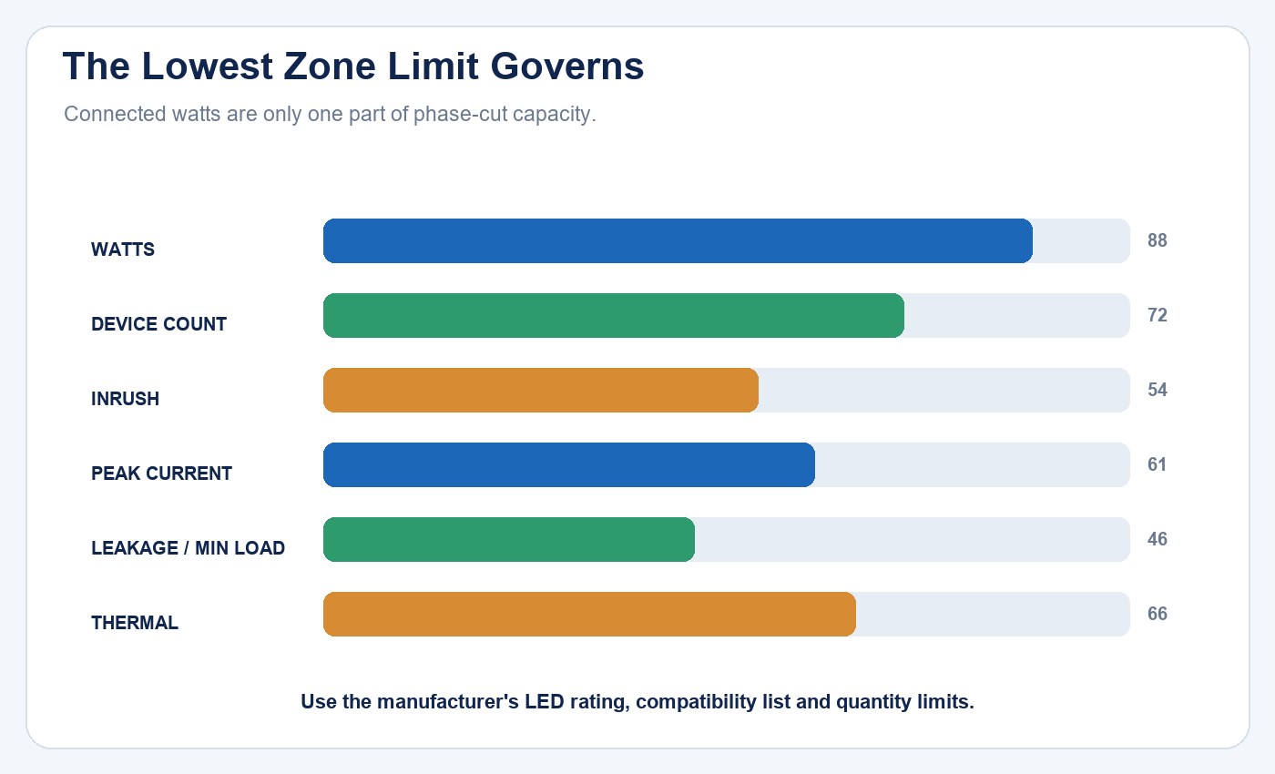
Zone capacity is constrained by several limits. The lowest approved limit governs the design.
Commission the Low End, Not Just Full Output
A system that turns on at full output has not yet demonstrated useful dimming. Test the complete intended range after warm-up. Lower the control slowly and record the point at which light output becomes unstable, lamps differ visibly, the load drops out or the driver produces objectionable noise.
Set low-end trim above the unstable region and verify reliable turn-on from that setting. Check for pop-on, where the light initially jumps to a higher level, and drop-out, where it turns off before the control reaches its minimum command. Verify high-end trim as well; some projects intentionally cap maximum output, while an incorrect limit can make a healthy system appear underpowered.
Observe every device on the zone. One sample operating acceptably does not prove that a larger zone will behave the same way. Test switch-on, switch-off, rapid command changes, sustained low level and recovery after loss of power. Document the dimmer mode and trims so later maintenance does not reset them unknowingly.
| Commissioning step | Observe | Record |
|---|---|---|
| Power on | Delay, synchronized start and protection behavior | Supply, quantity and initial setting |
| Sweep downward | Instability, shimmer, noise and mismatch | Lowest stable level |
| Start from low | Pop-on or failure to start | Start command and actual behavior |
| Switch off | Ghosting, pulsing or delayed extinction | Off-state condition |
| Restore power | Mode, trim and scene recovery | Firmware and retained settings |
Use the flicker, power factor and THD checklist when visual observation needs to be connected to measured electrical and light-modulation behavior.
Diagnose Common Phase-Control Symptoms
Flicker can arise from an incompatible driver-control pair, an unsuitable phase mode, operation below the stable low end, supply disturbance or a defective component. Ghosting while off can involve control leakage and the driver input. Delayed turn-on and pop-on may indicate that the driver needs a higher conduction point to start. Audible noise can come from the dimmer, driver or mechanical parts responding to the chopped waveform.
Do not assign a cause from the symptom alone. First confirm the exact models and settings, then compare the behavior with the manufacturers’ compatibility information. Change one controlled variable at a time. Line-voltage measurements and control replacement require qualified personnel.
The LED light failure diagnosis guide helps separate supply, driver, control and load faults when a dimming symptom persists outside the compatibility trial.
Manage Product Substitutions as a New Compatibility Decision
Substituting an LED lamp, driver or dimmer can change the electrical behavior of an entire zone. A replacement with the same wattage may have a different input circuit, inrush profile, preferred phase or low-end limit. DOE project experience documented zone redesign and compatibility rechecks after LED products were discontinued or redesigned.
Require submittals to preserve exact model numbers and approved alternates. If an alternate is proposed, repeat the compatibility review and mock-up. Record the result by zone rather than accepting a broad statement that both products are “phase dimmable.” This is especially important when multiple drivers share one dimmer.
The LED tube supplier evaluation guide explains how to connect sample approval, production identity and change control. For bulb-level driver questions, use the LED filament bulb driver selection guide; for component loading, thermal margin and version changes, see the LED driver reliability guide.
A Practical Selection Workflow
Start with the required user experience: target low-end level, smoothness, off behavior, fade response, acoustic limit and zoning. Select an LED driver that explicitly supports the intended control type. Then select a control for which the manufacturer provides compatible-load guidance at the project voltage and quantity.
Build a representative mock-up with the actual lamp or luminaire, driver, control and expected zone count. Commission the phase mode and trims, test all operating states and document the approved combination. For a bounded OEM review, contact New Lights with the driver model, dimmer model, supply, number of loads per zone and target dimming range.
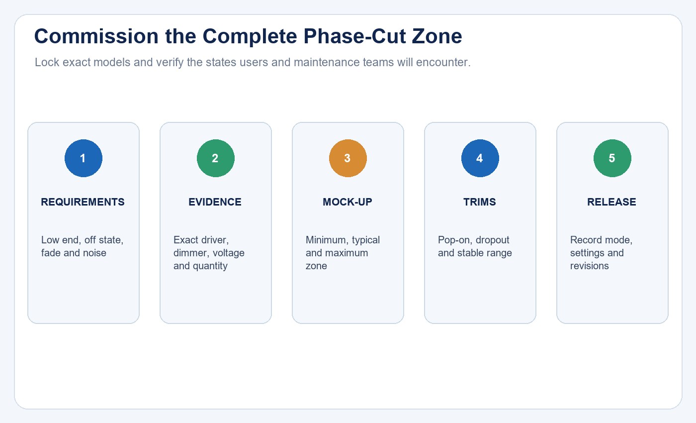
The correct answer is not that forward-phase or reverse-phase is inherently superior. The correct answer is the phase mode and control configuration that the exact driver manufacturer supports and the complete installed zone verifies.
Frequently Asked Questions
Is forward-phase the same as leading-edge dimming?
Yes. Forward-phase or leading-edge control cuts the beginning of each AC half-cycle. Reverse-phase or trailing-edge control cuts the end.
Is reverse-phase always better for LED lighting?
No. Many LED drivers support or prefer reverse-phase, but others require or perform better with forward-phase. Follow exact manufacturer compatibility data.
Is TRIAC dimming always forward-phase?
The term is often used loosely in product literature and does not establish complete system compatibility. Verify the actual accepted waveform, control model, voltage and load limits.
Is 0–10V a type of phase-cut dimming?
No. It is a separate analog control architecture, usually using dedicated control conductors in addition to driver power.
Why do LED lights flicker only at low level?
The driver-control combination may be below its stable operating range, or the phase mode, load, trim or component condition may be unsuitable. Confirm compatibility and commission the low-end trim.
Can I replace an LED driver with another model of the same wattage?
Not without rechecking. Input behavior, phase support, current output, voltage window, inrush, dimming range and protections can differ even when wattage matches.
Editorial Sources
- Lutron, Application Note #781: https://www.lutron.com/TechnicalDocumentLibrary/048781.pdf
- Lutron, Application Note #579: Color Tuning with Lutron Controls: https://www.lutron.com/TechnicalDocumentLibrary/048579.pdf
- U.S. Department of Energy GATEWAY, Dimming LEDs with Phase-Cut Dimmers: The Specifier’s Process for Maximizing Success: https://betterbuildingssolutioncenter.energy.gov/sites/default/files/attachments/2013_gateway_dimming.pdf