


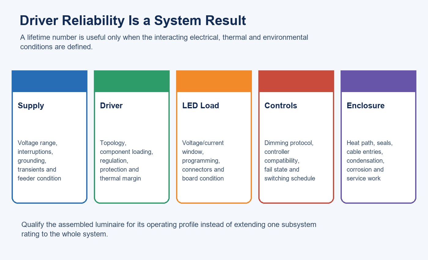
An LED streetlight power supply does not have one universal service life. Its reliability depends on the driver design, component loading, internal temperature, incoming power, surge exposure, enclosure conditions, control interface, LED load and installation quality. A useful reliability plan therefore begins with the complete luminaire and its operating environment, not with a generic promise that one component change will add a fixed number of years.
This distinction matters in procurement. LED package lumen-maintenance data describe one part of the lighting system. They do not, by themselves, establish the lifetime of the driver, controls, connectors, seals or complete luminaire. U.S. Department of Energy reliability guidance similarly treats solid-state lighting as a system whose interacting parts can age or fail in different ways.
The practical objective is not to predict an exact service date from a brochure. It is to identify the stresses that can be controlled, request evidence for the intended operating profile and collect field data that can improve the next specification.
1. Define What “Driver Life” Means
Before comparing products, define the event that counts as a failure. A driver may stop producing output, operate intermittently, drift outside its regulated output, fail to dim correctly or trigger repeated protective shutdowns. A connected streetlight may also appear to have a driver problem when the fault is in the controller, communication node, wiring or input supply.
The lifetime statement must also identify its conditions. At minimum, ask for the driver model and revision, input range, output load, ambient or case temperature, switching schedule, dimming profile and environmental assumptions. A number without those conditions is difficult to apply to a real road.
The project team should distinguish three different questions:
- How long is the LED package expected to maintain a stated light output under specified test conditions?
- How has the driver been qualified against electrical, thermal and environmental stress?
- What is the expected reliability of the complete luminaire in the actual installation?
These questions are related, but they are not interchangeable.
| Reliability question | Evidence that answers it | Common substitution to reject |
|---|---|---|
| Will the LED source maintain output? | Applicable source-level lumen-maintenance and temperature data | Treating source data as complete-luminaire life |
| Can the driver tolerate its electrical and thermal profile? | Driver qualification, derating, protection and in-luminaire thermal evidence | Quoting a lifetime number without conditions |
| Will the luminaire remain serviceable on this road? | Complete-system testing, commissioning and traceable field results | Assuming one successful bench sample represents the installation |
2. Control Driver Temperature in the Complete Luminaire
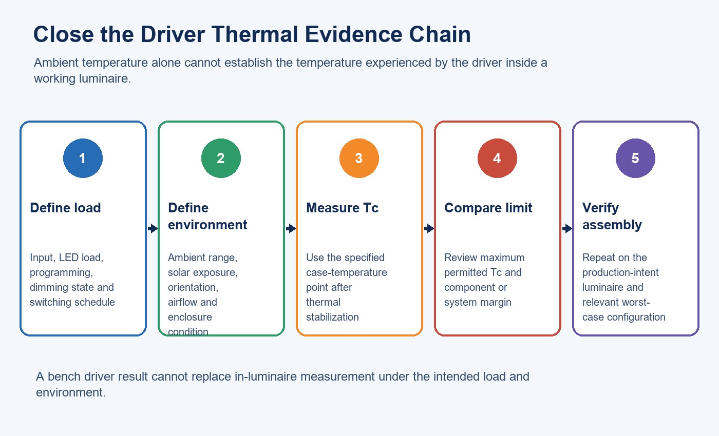
Temperature is one of the most important reliability variables for power electronics. The relevant value is not simply outdoor air temperature. The driver operates inside or near a luminaire where solar loading, LED heat, enclosure volume, mounting orientation, airflow and dirt accumulation can change its thermal condition.
Ask the supplier to identify the driver case-temperature measurement point and its maximum permitted value. Then request an in-luminaire thermal report for the intended LED load, input voltage, orientation and ambient range. A thermal image without measurement locations, operating conditions or stabilization time is not enough to validate a life claim.
Good thermal practice can include a suitable heat path, separation from major heat sources, controlled component loading and adequate design margin. DOE guidance also identifies topology, thermal design, component selection and derating as relevant to reliable driver performance. The evidence should apply to the actual assembly, not merely to a similar open-bench power supply.
Maintenance affects this boundary as well. Dirt, blocked drainage, damaged seals or an incorrectly closed service compartment can alter the environment after installation. Inspection instructions should therefore explain which surfaces, vents, gaskets and fasteners must remain in their designed condition.
For a broader explanation of temperature, current and system lifetime, use the LED thermal management and lifetime validation guide.
| Thermal record | Minimum detail | Decision supported |
|---|---|---|
| Operating configuration | Input, output current, LED load, dimming state and orientation | Whether the test represents the intended model |
| Environment | Ambient temperature, solar exposure assumption, airflow and enclosure state | Whether the thermal boundary is realistic |
| Measurement | Tc location, stabilization rule, instrument and measured value | Comparison with the driver limit |
| Margin review | Maximum permitted Tc and relevant component derating | Whether additional design or application margin is needed |
3. Match the Driver to the LED Load and Operating Profile
A driver should be evaluated at the real load rather than selected only by a nominal wattage label. Confirm the LED board voltage and current range, maximum and minimum loading, startup behavior and any programmable output settings. If one driver is used across several luminaire wattages, the approved configuration and programming record should be traceable by model and production batch.
Dimming changes the operating profile. Reduced output may lower thermal stress in some designs, but frequent switching, deep dimming, control faults or interface incompatibility can create different electrical conditions. Do not convert an energy-saving schedule into a life-extension percentage unless the complete driver and luminaire have been evaluated for that schedule.
For networked systems, jointly test the luminaire, driver and controller. Confirm the control protocol, wiring method, fail state, minimum dim level and behavior after power interruption. DOE testing of streetlight dimming has found meaningful performance variation among market-available driver implementations, which reinforces the need to verify the actual combination rather than rely on an interface label alone.
The LED driver, dimming and control compatibility guide provides a separate workflow for matching interfaces and testing minimum output, transitions and failure behavior.
4. Specify Surge Protection for the Installation
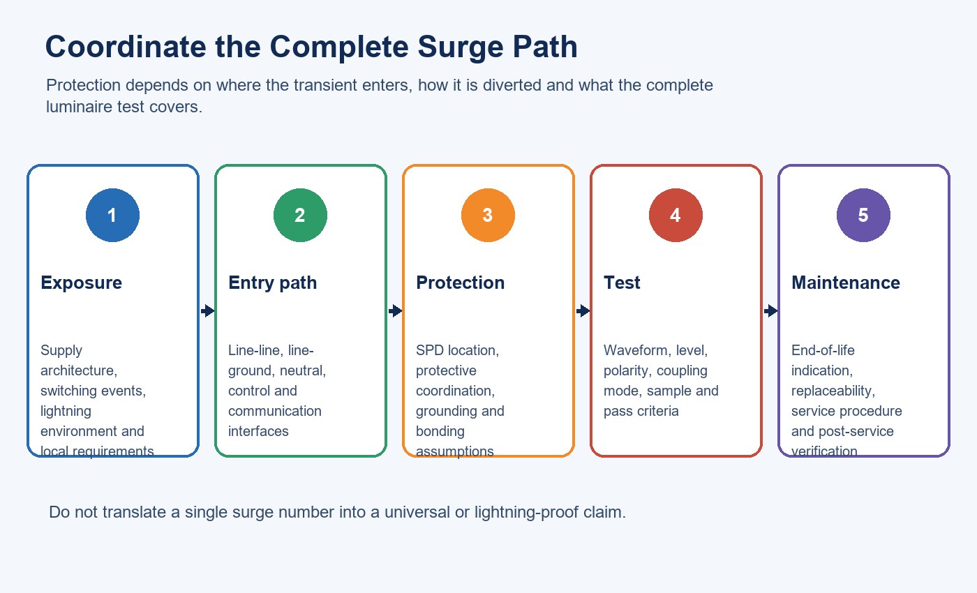
Streetlights can be exposed to switching transients and lightning-related surges through supply and grounding paths. Protection must be coordinated with the electrical environment, local requirements, luminaire architecture and maintenance strategy. One surge-protection number is not automatically suitable for every city, pole or distribution system.
A useful supplier submission identifies:
- the test method and waveform;
- the applied level and polarity;
- line-to-line and line-to-ground test configuration;
- the protective components and their location;
- grounding and bonding assumptions;
- pass or failure criteria;
- whether the result applies to the driver alone or the complete luminaire.
Also ask what happens after a protection device reaches the end of its useful condition. If it is replaceable, the service procedure and part identity should be documented. If it is not replaceable, the procurement team needs to understand the maintenance consequence. No responsible specification should describe a product as “lightning-proof.”
| Surge submission item | What to verify | Why it changes the decision |
|---|---|---|
| Test method | Waveform, level, polarity and coupling mode | Different configurations do not represent the same stress |
| Test boundary | Driver alone or complete luminaire | Driver-only evidence may omit wiring, SPD and enclosure interfaces |
| Grounding assumptions | Line, neutral, protective earth and bonding arrangement | The diversion path affects component stress |
| Service consequence | Replaceable SPD, indicator and approved replacement | Protection end-of-life can become a maintenance event |
5. Evaluate Power Quality, Not Only Nominal Voltage
A label showing an input-voltage range does not describe every site condition. Undervoltage, overvoltage, repeated interruptions, harmonics, neutral or grounding faults and transient events can affect electronic streetlighting equipment. DOE connected-streetlighting research specifically notes that older electrical infrastructure may not always provide consistent service and has examined LED streetlight susceptibility to power-quality issues.
During a pilot, record voltage and relevant disturbances at representative locations rather than assuming all poles receive the same supply. If faults cluster by feeder, time or weather event, investigate the infrastructure as well as the luminaire. Replacing drivers repeatedly without checking the supply can hide a system problem and produce misleading supplier-failure statistics.
The driver submission should state its steady-state input limits and protective behavior. Project-specific requirements may also call for power factor, harmonic, immunity or other test evidence, but the applicable standards and limits must be selected for the target market and installation. Do not copy a list of standards into a specification without confirming scope and report coverage.
6. Manage Moisture, Condensation and Enclosure Workmanship
An enclosure IP rating is relevant to ingress protection, but it is not a universal reliability certificate. It does not by itself prove resistance to condensation, salt exposure, corrosion, thermal cycling, electrical surge or poor field assembly. The complete luminaire design should be reviewed for gaskets, cable entries, drainage, interfaces, pressure behavior and service access.
Ask whether the ingress test applies to the production configuration, including cables, connectors, controls and service covers. Review assembly controls for gasket placement, fastener torque and cable-gland installation. A validated design can still be compromised by inconsistent production or field workmanship.
Where condensation is a credible risk, request evidence that addresses the intended temperature and humidity cycle. Avoid assuming that adding an unverified vent or sealant will improve reliability; either change can alter the enclosure behavior and may invalidate existing test coverage.
7. Require Component Derating and Qualification Evidence
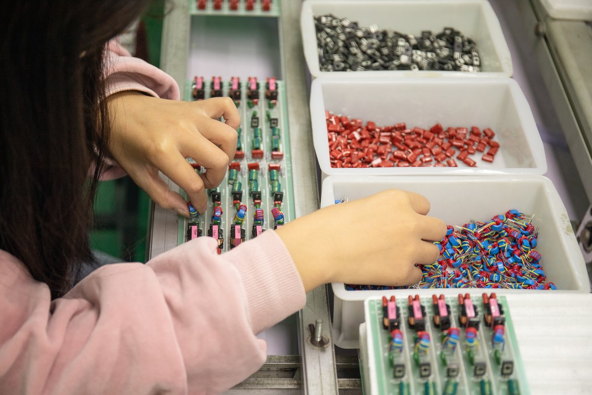
Electrolytic capacitors receive attention because temperature can strongly affect their life, but a driver contains many other parts and interfaces. Protection devices, semiconductors, magnetics, solder joints, connectors and control circuits can also contribute to failure. Treating every driver problem as a capacitor problem prevents proper root-cause analysis.
Supplier review should therefore cover component voltage, current and temperature margin; critical-component traceability; qualification tests; manufacturing controls; and the conditions behind any calculated lifetime. DOE lifetime guidance recommends qualification against stresses such as temperature, humidity, thermal cycling, shock and vibration, with test conditions and results reported clearly.
Burn-in or screening can help identify some early defects, but it cannot compensate for an inadequate design. Ask what failure mechanisms the test is intended to reveal, what sample size was used and how production changes are controlled after qualification.
When comparing supplier evidence, use the LED lighting supplier and factory audit checklist to connect critical components, change control and process verification.
8. Design for Inspection and Service
Reliability includes the ability to identify and correct a problem efficiently. A replaceable driver or surge-protection module may reduce maintenance disruption, but only if the replacement is electrically and mechanically compatible and the service action preserves the luminaire’s safety and ingress performance.
The maintenance file should include model and batch identification, wiring information, approved replacement parts, isolation procedure and post-service checks. For connected lights, save controller and firmware identity where relevant. Unauthorized substitutions can change output current, dimming behavior, thermal loading or protective coordination.
For each failure, record the pole or circuit, date, weather, supply observations, operating hours if available, symptom, driver and luminaire serial data, photos and the result of any authorized component swap. Preserve failed parts when a recurring pattern requires laboratory analysis.
9. Use Field Data to Improve the Specification
A pilot installation can reveal conditions that a generic datasheet cannot. Select representative thermal, electrical and environmental locations, not only the easiest poles to access. Establish the baseline before installation and define inspection intervals and failure categories in advance.
When reviewing results, separate driver failures from controller, connector, LED-board, enclosure and infrastructure faults. Report the denominator as well as the number of incidents. Five failures have a different meaning in a population of 100 luminaires than in a population of 20,000, and a clustered feeder event is different from random unit failures.
Use this evidence to refine requirements for the next batch. The objective is a closed loop between specification, supplier evidence, production traceability, commissioning and field performance—not a single optimistic service-life number.
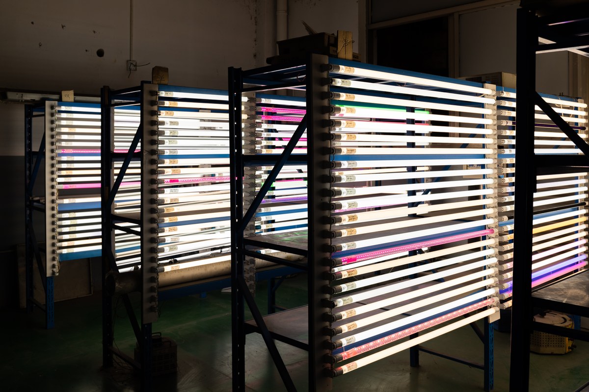
| Validation stage | Representative output | Release question |
|---|---|---|
| Design review | Load range, derating, thermal path and protection architecture | Are the important stresses controlled by design? |
| Qualification | Electrical, thermal, environmental and control test records | Does the production-intent sample meet defined criteria? |
| Pilot | Representative poles, baseline measurements and inspections | Does the system behave as expected at the site? |
| Field monitoring | Failures by model, lot, location, circuit and mode | Is there a repeatable pattern that requires corrective action? |
The LED lighting sample evaluation checklist can structure the production-intent sample and pilot review. For lifecycle planning, see lighting maintenance and spare-parts planning.
Procurement Checklist
Before approving an LED streetlight power supply, confirm that the submission includes:
- Driver make, model, revision and approved luminaire configuration.
- Input and output limits, LED load and programming information.
- Case-temperature point, limit and complete-luminaire thermal results.
- Component derating and critical-component control.
- Surge architecture and complete test conditions.
- Environmental, ingress and relevant cycling evidence.
- Dimming or network-controller compatibility results.
- Failure definition and conditions behind any lifetime statement.
- Replacement, service and post-repair sealing instructions.
- Field-return classification and corrective-action process.
Conclusion
Improving LED streetlight driver reliability means controlling known stresses and demanding evidence that matches the installation. Start with the operating profile, verify temperature in the complete luminaire, match the driver to the LED load, coordinate surge protection, investigate power quality, preserve enclosure integrity and test the actual control combination. Then use traceable field records to check whether the design assumptions hold.
For current product context, review the New Lights all-in-one LED solar street light and the wider outdoor, garden and solar lighting range. Exact driver, thermal, surge, control and environmental requirements should be confirmed for the intended project configuration. To review a defined application, contact New Lights with the luminaire model, electrical conditions, control requirements and operating environment.
FAQ
Does a 50,000-hour LED rating mean the streetlight driver will last 50,000 hours?
No. LED package lumen-maintenance information and driver or complete-luminaire reliability are different measures. Request conditions and evidence for each subsystem and the assembled luminaire.
Is lower driver temperature always better?
Lower operating temperature generally reduces stress on many electronic components, but the applicable limit and predicted effect depend on the actual driver design, measurement point, load and test method. Use the model-specific thermal report.
Are electrolytic capacitors the only reason LED drivers fail?
No. Capacitors can be important, but protection components, semiconductors, magnetics, solder joints, connectors, controls and external electrical conditions can also contribute.
Does an IP65 streetlight automatically protect the driver from every outdoor condition?
No. IP testing addresses defined dust and water ingress conditions. It does not automatically establish performance against condensation, corrosion, thermal cycling, surge or incorrect assembly.
What surge rating should every LED streetlight use?
There is no single universal value. The project must consider the supply system, grounding, lightning exposure, local requirements, luminaire architecture and maintenance plan, then verify the complete test configuration.
Can dimming extend driver life?
It may change load and temperature, but a universal life-extension claim is not justified. Verify the actual driver, luminaire and controller combination across the planned dimming schedule.
Editorial Sources
- U.S. Department of Energy, “LED Systems Reliability Consortium”: https://www.energy.gov/cmei/ssl/led-systems-reliability-consortium
- U.S. Department of Energy, “LED Luminaire Lifetime Recommendations for Testing and Reporting”: https://www.energy.gov/eere/ssl/downloads/led-luminaire-lifetime-recommendations-testing-and-reporting-0
- U.S. Department of Energy, “LED Luminaire Lifetime: Recommendations for Testing and Reporting”: https://www1.eere.energy.gov/buildings/publications/pdfs/ssl/led_luminaire-lifetime-guide_june2011.pdf
- U.S. Department of Energy, “Connected Streetlighting Systems”: https://www.energy.gov/cmei/ssl/connected-streetlighting-systems
- U.S. Department of Energy, “The Energy and Operational Impacts of Using 0-10V Control for LED Streetlights”: https://www.energy.gov/cmei/ssl/articles/energy-and-operational-impacts-using-0-10v-control-led-streetlights
- U.S. Department of Energy, “On the Way: Automated Fault Detection and Diagnostics for LED Street Lighting Systems”: https://www.energy.gov/cmei/ssl/articles/way-automated-fault-detection-and-diagnostics-led-streetlighting-systems
- New Lights, “LED Solar Lighting” catalogue: https://www.new-lights.com/new-lights/2024/12/06/ledsolarlighting.pdf
- New Lights, “All-in-One LED Solar Street Lights”: https://new-lights.com/products/solar-lighting/solar-street-lights/led-solar-street-light/












