


A window-style artificial skylight is an electric luminaire designed to create a bright, sky-like view on an interior wall. Installing one successfully requires more than fitting a luminous panel into a rectangular opening. The product, support frame, electrical supply, heat path, finish, controls and service access must work as one coordinated assembly.
The practical sequence is straightforward: identify the exact product, classify the opening, assign each interface, approve a coordinated section, test a representative installation and release the final work only after the hold points pass. This guide focuses on that workflow for an interior wall installation. It does not cover roof skylights or exterior fenestration.
Start by Classifying the Opening
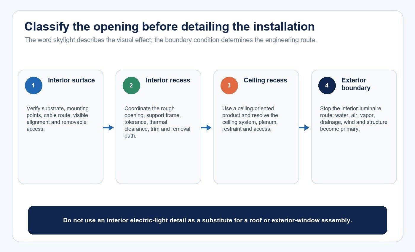
The word “skylight” can send a project in the wrong direction. The U.S. Department of Energy describes daylighting as the use of sunlight admitted through windows or skylights, while a window-style artificial skylight uses electric light. The visual idea may resemble a window, but the construction and performance questions are those of a luminaire integrated with an interior wall.
Classify the proposed location before selecting hardware or finishes:
| Proposed condition | Primary design route | Key consequence |
|---|---|---|
| Surface-mounted on an interior wall | Wall-mounted luminaire | Confirm substrate, load path, wiring route and removable access |
| Recessed into an interior partition | Luminaire plus framed opening | Coordinate rough opening, support subframe, thermal clearance, trim and service removal |
| Recessed into a ceiling | Recessed-luminaire project | Use a ceiling-oriented product and resolve the ceiling system, plenum and access separately |
| Exterior wall, window replacement or roof opening | Building-envelope and fenestration project | Stop the interior-luminaire workflow; water, air, vapor, wind, drainage and structural design become primary |
DOE Building Science Education describes roof-skylight flashing as part of the roof water-management system. A bead of sealant around an electric light panel is not an alternative to that system. If the opening separates indoor and outdoor conditions, the project needs a product and detail intended for the building envelope.
Match the Product to the Intended Orientation
Begin with a model-specific product record rather than a generic rendering. Record the model, overall dimensions, weight, mounting orientation, input, driver location, controls, approved mounting points, environmental classification and required clearances.
The New Lights X Series window-style artificial skylight provides a concrete example of the wall-oriented product category. Its product page should be used to identify the current model and published configuration; the installation drawing and project submittal should then define the mounting interface for the actual order.
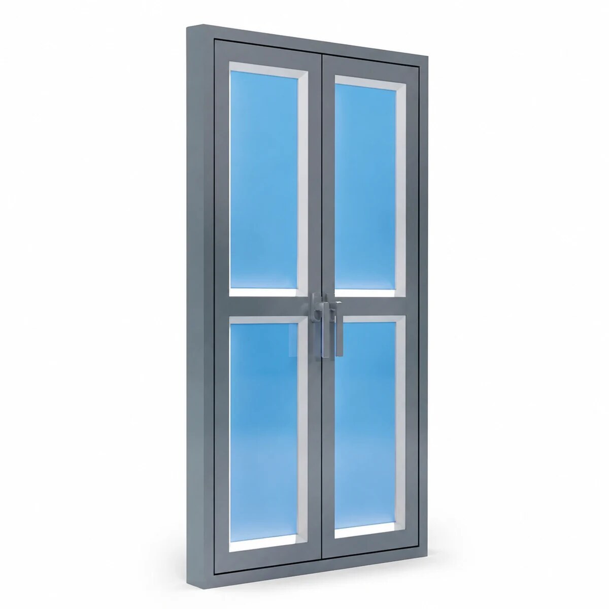
A wall-oriented product should not be exchanged casually with a ceiling-recessed series. Orientation changes the support direction, optical view, heat movement, cable routing and service procedure. Even when two products create a similar sky effect, their installation boundaries may be different.
Build One Coordinated Section Before Construction
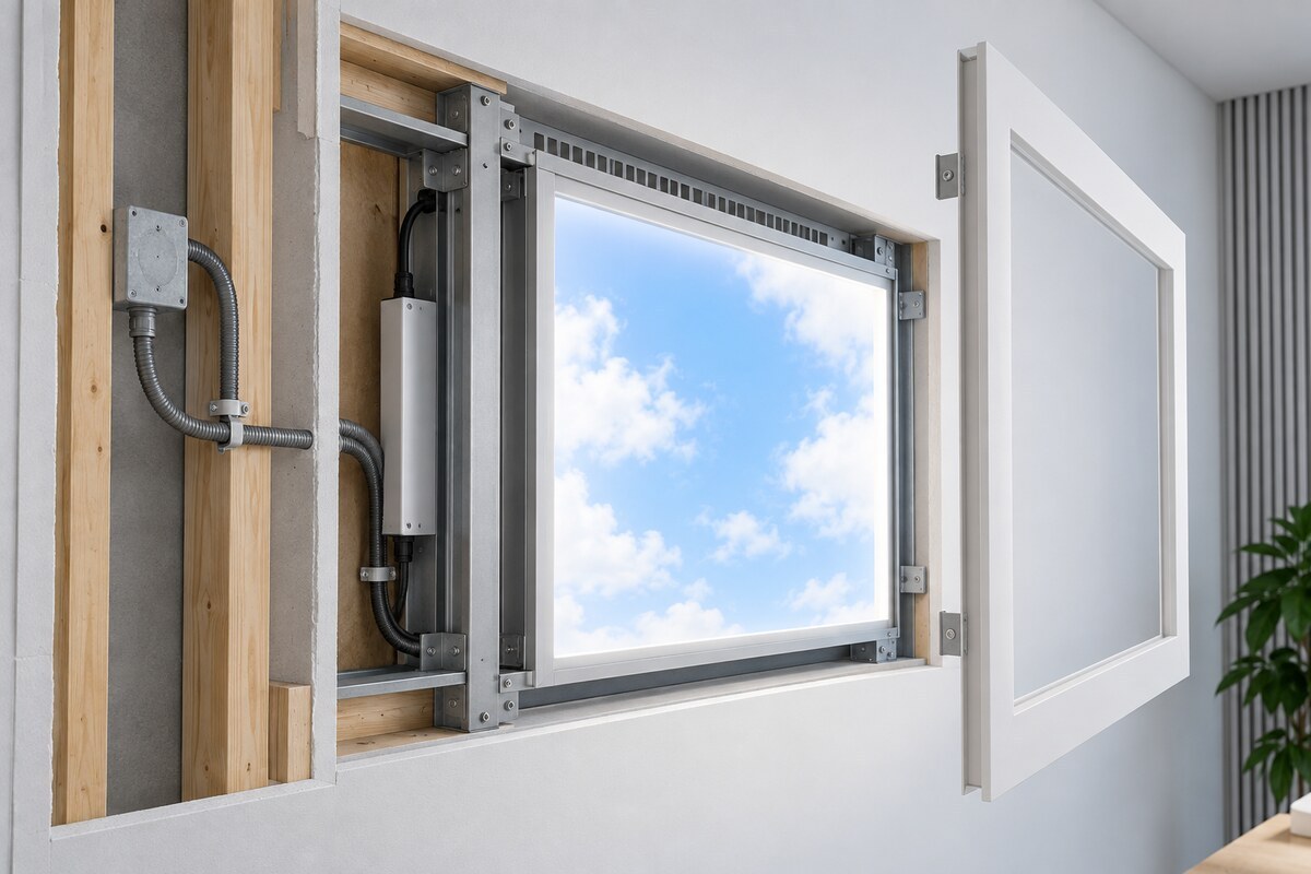
Plan the installation in section, not only in elevation. An elevation can show a neat rectangle while hiding the exact issues that determine whether the assembly can be built and maintained.
The section should show:
- the finished wall and structural substrate;
- the rough opening and dimensional tolerance;
- the product envelope and approved mounting points;
- the primary support frame and any permitted adjustment;
- the cable route, junction point and driver location;
- ventilation or thermal clearance required by the selected model;
- trim, shadow gap or finish-return geometry;
- the removal direction and temporary support needed for service.
The drawing should separate known product dimensions from site dimensions. A useful fit relationship is:
rough opening = approved product envelope + installation tolerance + permitted adjustment and service allowance
The values in that relationship must come from the selected product and project detail. Increasing the opening “for flexibility” can leave the support too far from the mounting points. Reducing it to improve the reveal can make installation or future removal impossible.
Assign Every Interface to an Owner
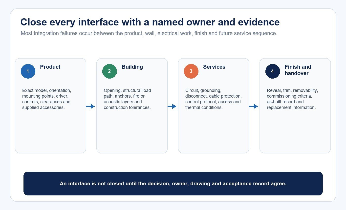
Integration failures often occur between trades rather than inside the luminaire. A responsibility matrix makes those boundaries visible before procurement.
| Interface | Required decision | Typical evidence | Responsible party |
|---|---|---|---|
| Product identity | Exact model, orientation and supplied accessories | Product schedule, datasheet, order code | Specifier and supplier |
| Opening | Size, depth, squareness, substrate and concealed services | Survey record and construction section | Architect or contractor |
| Structural support | Load path, frame, anchors and restraint | Approved support detail and calculations where required | Structural designer and contractor |
| Electrical | Circuit, grounding, disconnect, driver, wiring method and access | Electrical drawing and product instructions | Electrical designer and electrician |
| Controls | Protocol, controller location, scenes and failure behavior | Control schedule and sequence of operation | Controls integrator |
| Finish | Reveal, trim, joint, surface protection and removability | Interior elevation and detail | Architect and finish trade |
| Commissioning | Visual, electrical, thermal and control acceptance | Test plan and signed record | Commissioning lead and owner |
The supplier can define product requirements, but the supplier does not automatically own the building substrate, branch circuit or wall finish. Conversely, the contractor should not move product mounting points or enclose a driver without confirming that the resulting configuration remains acceptable.
Survey the Existing Wall as a System
Measure width, height, depth, plumb, level, squareness and surface flatness at multiple points. Record the smallest usable dimension, not only the nominal center measurement. Photograph both faces of the wall and identify studs, masonry, reinforcement, conduits, pipes, fire or acoustic layers and nearby doors or glazing.
The substrate matters because the visible finish is rarely the load-bearing layer. Gypsum board, decorative panels, trim and adhesives can complete the appearance, but they should not be treated as the structural load path unless the approved detail explicitly assigns that role.
For retrofit work, look for cracks, corrosion, moisture staining, loose finishes and previous openings. A damaged or wet cavity should be resolved before the luminaire closes the area. If the location is close to exterior glazing, include surface-temperature and condensation review even when the artificial skylight remains indoors.
Design the Support and Retention Path
Trace the load from the product’s approved mounting points to verified building structure. The support detail should identify frame members, anchors, quantity, location, edge distance, substrate, access and corrosion environment. Where the product is above or adjacent to occupied space, assess whether a secondary restraint is required by the project or jurisdiction.
The support frame also controls optical appearance. A twisted or uneven frame can distort the visible reveal, concentrate pressure at the product edge or create bright and dark gaps. Separate alignment features from final retention: a shim may establish position, but it does not automatically become a structural connection.
Account for the installation sequence. If the frame is completed before the product arrives, define a dimensional hold point. If the product must be used to locate brackets, protect the optical surfaces and provide temporary support while anchors are installed.
Coordinate Electrical Supply, Driver and Controls
Treat the assembly as fixed electrical equipment. Confirm the supply voltage and frequency, branch circuit, overcurrent protection, grounding, disconnecting method, cable type, junction enclosure, strain relief and permitted fixture-wire use for the jurisdiction. OSHA 1910.305 addresses fixture wiring, support, protection and identified location suitability within its US workplace scope; the project still needs the rules applicable to its own jurisdiction. OSHA 1910.305 addresses fixture wiring, support, protection and identified location suitability within its US workplace scope; the project still needs the rules applicable to its own jurisdiction.
UL Solutions identifies UL 1598 and UL 8750 within its indoor-lighting service context. IEC 60598-1 covers general luminaire safety requirements, while IEC 60598-2-2 addresses recessed luminaires where that product classification applies. These references help define the evidence to request; they do not replace the installation instructions or local code review for a selected model.
Locate the driver and connectors where their temperature limits and service requirements can be met. Do not bury serviceable controlgear behind permanent finishes. Keep wiring protected from sharp edges and removable parts, and show enough cable management that the product can be supported safely during service.
For dimming or smart control, document the protocol, controller, addressing, scene range, manual override, power-loss recovery and ownership of credentials. The handover should allow the building team to operate and reset the system without reconstructing the installer’s setup.
Resolve Heat, Ventilation and Finish Together
The product, driver and wall cavity form a thermal system. Heat that can escape from a surface-mounted unit may accumulate when the same form is recessed. Insulation, acoustic infill, fire stopping and tight decorative trim can further change the temperature around the controlgear and optical components.
Use the selected model’s rated ambient conditions and clearance instructions as design inputs. Keep required openings clear after finish work. When the cavity is unusual or the installation is repeated across a project, measure temperatures on a representative mockup under a defined operating condition before approving the rollout.
Finish materials also need a defined purpose. A trim may hide tolerance, a gasket may control dust, and a sealant may close an interior cosmetic joint. None of those functions should be mislabeled as exterior waterproofing. Check material compatibility so sealants, tapes or cleaners do not haze optical surfaces or damage coatings.
Preserve a Real Service Route
Service access should be demonstrated, not represented by a note saying “accessible.” Show the removal direction, clear zone, temporary support point, connector reach, driver access and sequence for replacing components. Confirm that furniture, millwork, glazing, doors or another room will not block the route after occupancy.
Ask four practical questions:
- Can the visible panel be removed without damaging the wall finish?
- Can the driver and controls be reached without disconnecting unrelated building systems?
- Can a technician support the product safely while disconnecting it?
- Can the owner identify compatible replacement parts and restore control settings?
The artificial skylight troubleshooting and maintenance guide can help the team plan future diagnostic access, while the broader artificial skylight project planning guide covers visual intent, room integration and mockup strategy.
Use a Representative Mockup to Close the Decision Loop
A mockup should reproduce the difficult conditions of the final installation: opening geometry, orientation, viewing distance, surrounding finishes, control range, driver location and thermal enclosure. A loose sample on a table cannot reveal wall glare, edge leakage, finish tolerance or service difficulty.
Worked example: an opening that is not square.
Suppose the survey finds that the top of an existing opening is narrower than the bottom and one side is out of plumb. Forcing the product into the opening transfers construction error into the luminaire and finish. Filling the gap with an oversized cosmetic joint hides the symptom but leaves the support and service geometry unresolved.
The better sequence is to define the minimum usable opening, compare it with the approved product envelope and tolerance, correct or reframe the substrate, install an adjustable but fully retained subframe, and then confirm the final reveal with a sample. This closes both the structural and visual decisions without changing the product.
Use the LED lighting sample evaluation checklist to document identity, configuration, test purpose and acceptance criteria. If model evidence or a project-specific sample is needed, contact New Lights with the opening survey, intended orientation, electrical supply, controls and service constraints.
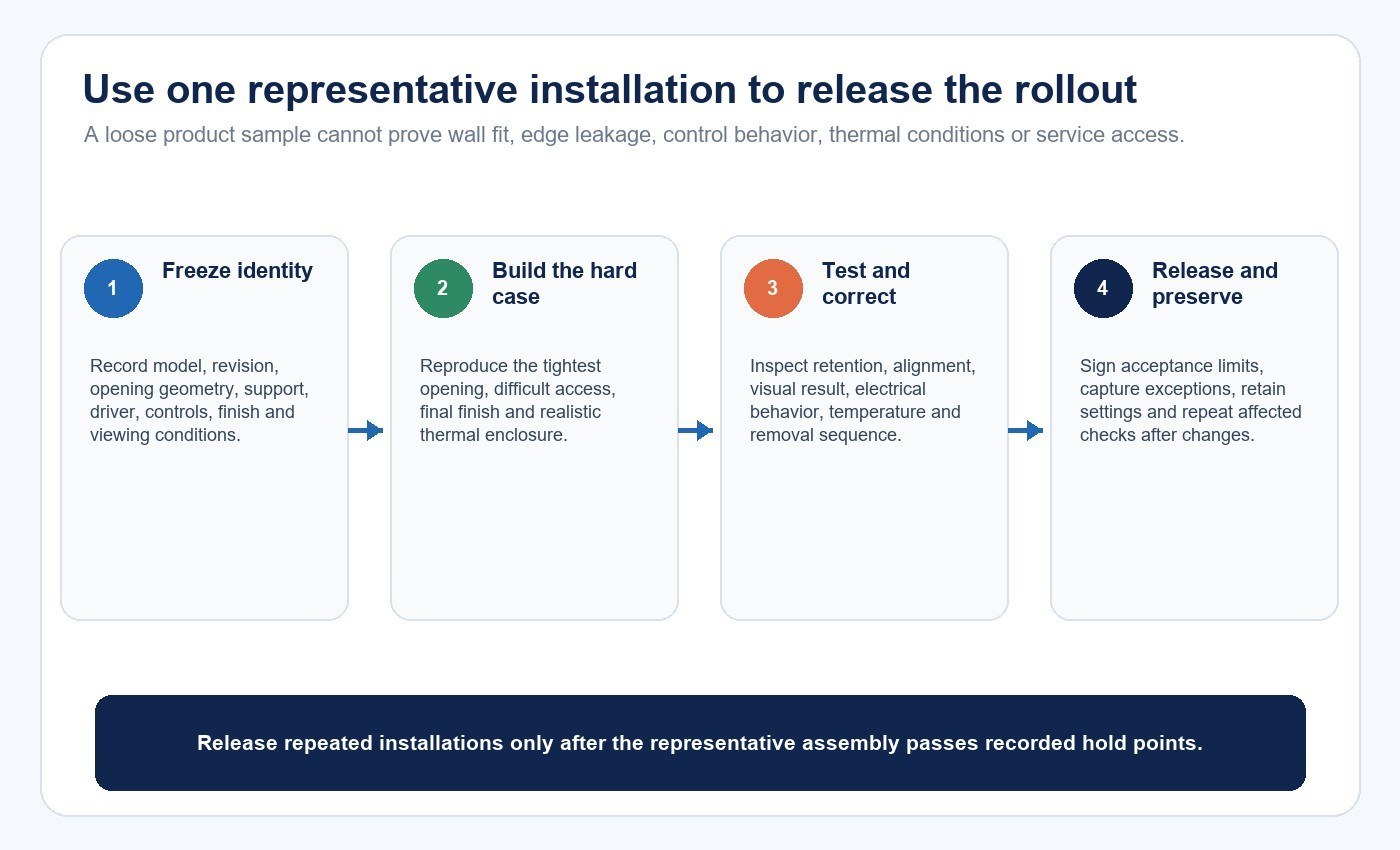
Commission Against Recorded Acceptance Criteria
Commissioning should test the completed installation, not just confirm that the panel turns on.
| Check | Acceptance question | Record |
|---|---|---|
| Mechanical | Is the product retained, aligned and free from movement or finish pressure? | Fastener/retention inspection and photographs |
| Electrical | Are supply, grounding, enclosure, cable protection and disconnect consistent with the approved design? | Electrical test and inspection record |
| Visual | Are brightness, uniformity, edge leakage, glare and reflections acceptable from agreed viewpoints? | Scene settings, photographs and observations |
| Controls | Do all commands, scenes, limits, manual override and power recovery behave as specified? | Functional test sheet |
| Thermal | Do the product, driver and cavity remain within the accepted project conditions? | Stabilized operating measurements where required |
| Service | Can the product and controlgear be accessed and supported using the documented method? | Demonstrated service sequence |
Complete the handover with as-built drawings, model and serial records, control settings, cleaning instructions, spare-part references, warranty information and unresolved exceptions. The New Lights artificial skylight solution page provides the wider application context, and the factory and manufacturing page explains the production and quality environment behind project coordination.
Frequently Asked Questions
Is a window-style artificial skylight a real window?
No. It is an electric lighting product designed to create a window-like visual feature. It should not be used as exterior glazing, ventilation or weather protection unless a separate product is explicitly designed and approved for those functions.
Can it be installed in an existing window opening?
Only after the opening is classified. An interior opening may be suitable when the product, support, wiring, thermal conditions and service route are coordinated. An opening that forms part of the exterior envelope requires a different fenestration and water-management design.
Is silicone enough to seal the installation?
Sealant can perform a defined interior joint or appearance function. It does not create a complete roof or exterior-wall water-control system, and compatibility with the product and adjacent finishes still needs to be established.
Should the driver be hidden inside the wall?
Only when the approved product configuration, temperature conditions, electrical requirements and service plan allow it. A serviceable driver should remain reachable after the finish is complete.
What should be approved before ordering?
Approve the exact model, orientation, opening survey, support concept, electrical supply, controls, finish intent, service route, required evidence and mockup plan. Final construction details should then be based on the selected model and site conditions.
Editorial Sources
- U.S. Department of Energy, “ZEB Technologies: Lighting & Daylighting”: https://www.energy.gov/cmei/buildings/zeb-technologies-lighting-daylighting
- DOE Building Science Education, “Flashing around a Skylight without Roof Removal”: https://bsesc.energy.gov/energy-basics/flashing-around-skylight-without-roof-removal
- UL Solutions, “Indoor and Decorative Lighting”: https://www.ul.com/services/indoor-and-decorative-lighting
- Occupational Safety and Health Administration, “1910.305—Wiring Methods, Components, and Equipment for General Use”: https://www.osha.gov/laws-regs/regulations/standardnumber/1910/1910.305
- International Electrotechnical Commission, “IEC 60598-1:2024—Luminaires, Part 1”: https://webstore.iec.ch/en/publication/66620
- International Electrotechnical Commission, “IEC 60598-2-2:2023—Recessed Luminaires”: https://webstore.iec.ch/en/publication/68002












