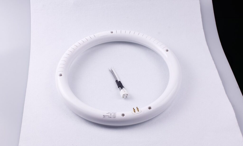
A double-sided T8 LED tube should be compared as part of a complete lighting system, not by lamp lumens or a “360-degree” label alone. The useful decision depends on where the tube sends light, how the host fixture redirects or absorbs it, which electrical retrofit route applies, and whether the exact lamp, installation and warranty evidence match the project.
Start by separating optical sidedness from electrical endedness. Then compare the candidate in the actual fixture or lightbox, measure useful output and installed power, review temperature and controls, confirm the applicable certification record, and read the warranty as an operating contract.
Separate Three Different Tube Descriptions
“Double-sided,” “double-ended” and “Type A/B/C” answer different questions. Treating them as synonyms can lead to the wrong product comparison or an unsafe installation assumption.
| Term | What it describes | Evidence to request | What it does not establish |
|---|---|---|---|
| Double-sided or broad-emission | The luminous surfaces or angular light distribution around the tube | Cross-section, photos, intensity distribution and IES/photometric data | Which pins receive power |
| Single-ended or double-ended power | The electrical connection topology at the lamp holders | Model wiring diagram, markings and installation instructions | Beam distribution or useful fixture output |
| Type A | Operation through an identified compatible fluorescent ballast | Exact ballast compatibility list and lamp instructions | Compatibility with every ballast |
| Type B | Internal-driver lamp connected to line voltage in an approved configuration | Retrofit-kit scope, socket/wiring requirements, labels and instructions | That bypass is universally preferable |
| Type C | Lamp operated by a separate external LED driver | Matched lamp-driver system documents and installation instructions | Interchangeability with unrelated drivers |
| Type A/B | More than one approved operating route | Separate evidence for each permitted mode | That the same performance applies in both modes |
The single-ended versus double-ended T8 article owns the electrical topology question. This article focuses on whether broad optical emission adds useful value in a particular host fixture and how to compare the complete offer.
Define the Optical Job Before Comparing Lamps
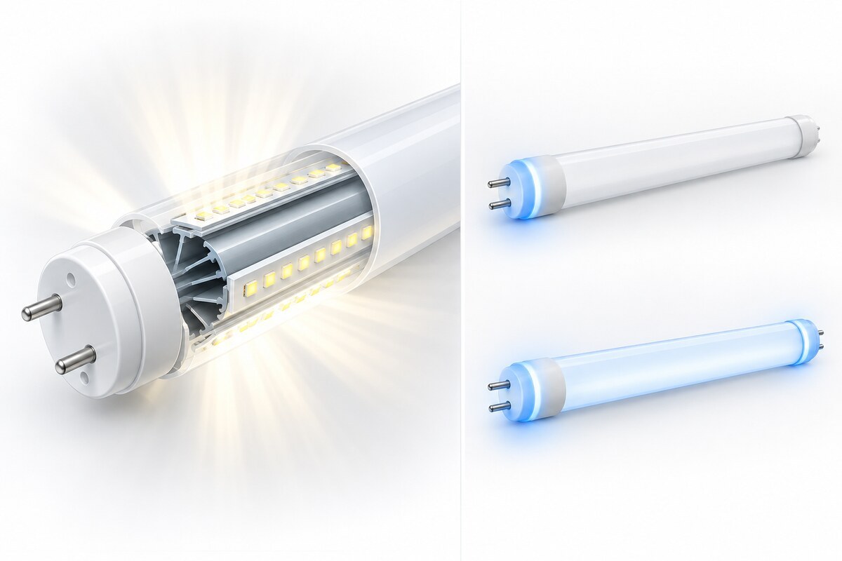
A conventional directional LED tube often directs most light toward one side of the host. A double-sided or 360-degree-style tube sends more light around the tube profile. That can be useful when the host is designed to collect rearward output, illuminate two opposing faces, or distribute light around an exposed tubular source.
It is not automatically an advantage. Rearward light can strike a high-reflectance surface and return to the useful plane, or it can be absorbed by a dark housing, trapped behind a diffuser, create unwanted brightness, or miss the task area. The tube’s angular intensity and the host geometry must be evaluated together.
The New Lights 360-degree double-sided T8 LED tube family is designed around LED arrays positioned around an internal aluminum heat sink. The current family includes models for double-sided lightboxes and similar installations that use light around the tube profile. That product direction is a useful example of a defined optical job—not evidence that broad emission improves every fluorescent retrofit.
Map the Host Fixture Before Selecting the Tube
Record the host manufacturer, fixture type, dimensions, number and spacing of lamps, lamp-holder orientation, reflector shape and reflectance, diffuser transmission, ventilation, ballast or driver, wiring, controls and surrounding surfaces. Photograph the fixture both assembled and open.
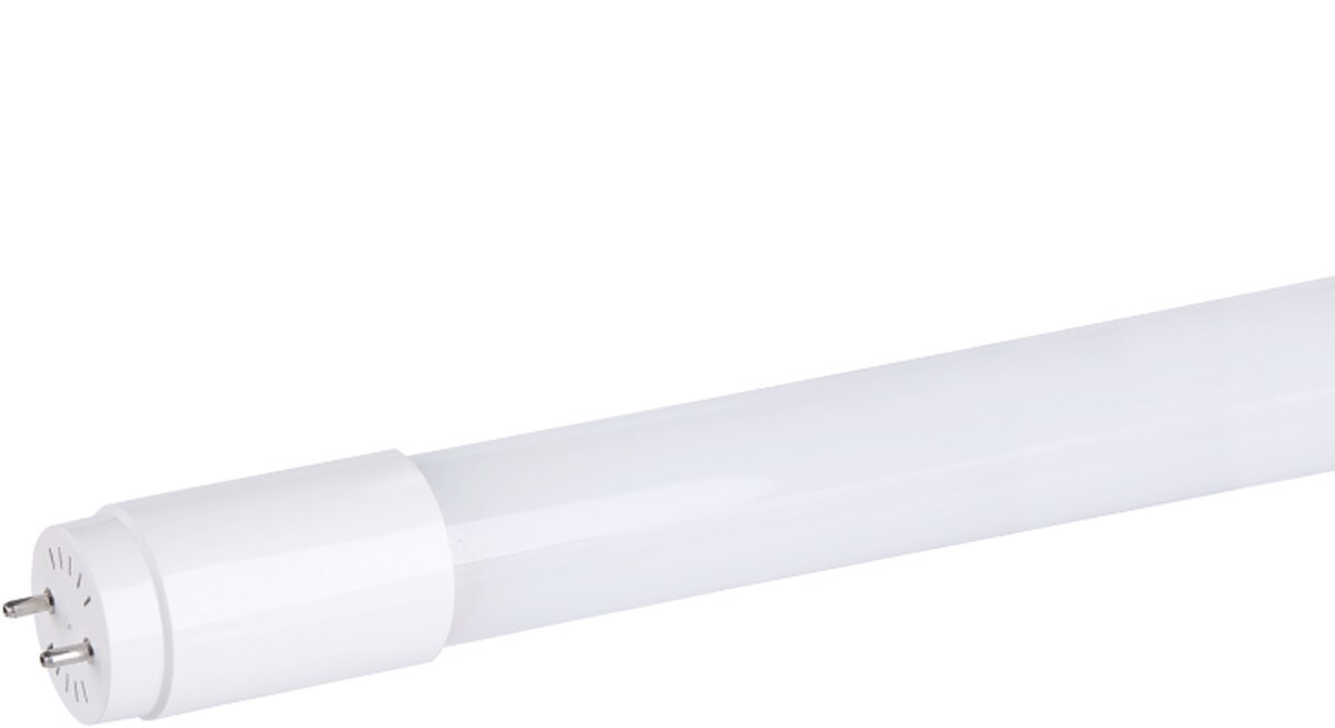
Physical fit includes more than T8 diameter and G13 pins. Check end-cap clearance, rotation, lamp-holder engagement, retention, diffuser distance and the final direction of each luminous surface. A tube that rotates in the socket can change distribution even when electrical operation remains normal.
Inspect for brittle wiring, damaged lamp holders, corrosion, heat discoloration, loose parts and prior field modifications. A new lamp does not correct an unsafe host. The broader commercial LED tube selection guide can be used for the initial retrofit inventory before this specialized optical comparison begins.
Compare Bare-Lamp Data and Host-System Results Separately
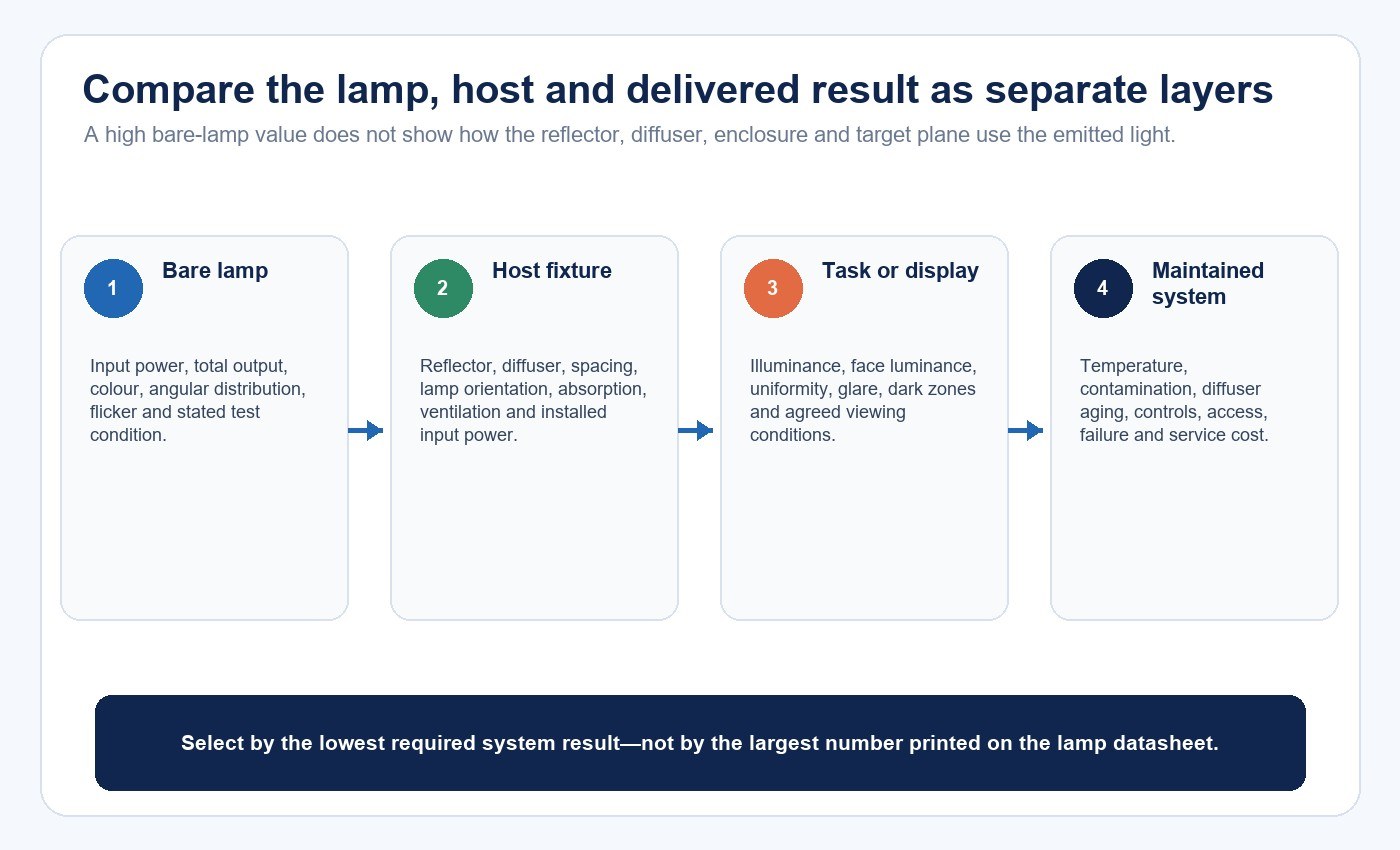
Bare-lamp testing is useful for comparing the lamp itself under a stated condition. It does not predict how much light reaches the work plane or both faces of a sign cabinet after reflector, diffuser and housing losses.
DLC’s current SSL V6.0 material treats linear replacement lamps as a defined product category and specifies lamp-level testing conditions for Type A, Type B and Type C pathways. That program evidence can support product screening, but the application decision still needs the real host fixture.
Use two evidence layers:
| Comparison layer | Useful measurements | Decision it supports | Common error |
|---|---|---|---|
| Bare lamp | Input power, total output, efficacy, color, angular distribution, flicker and temperature condition | Compare exact lamps under aligned test boundaries | Assuming the highest lm/W wins in every host |
| Lamp plus host | Installed input power, luminaire output, zonal distribution, face luminance, uniformity, glare and temperature | Select the tube for the actual fixture or lightbox | Applying one reference housing result to a different enclosure |
| Room or display | Illuminance, vertical brightness, sign-face uniformity, spacing and visual acceptance | Confirm the project outcome | Using a lamp label as a lighting design |
| Maintained system | Dirt, diffuser aging, driver/ballast behavior and service access | Estimate lifecycle performance | Comparing only initial output |
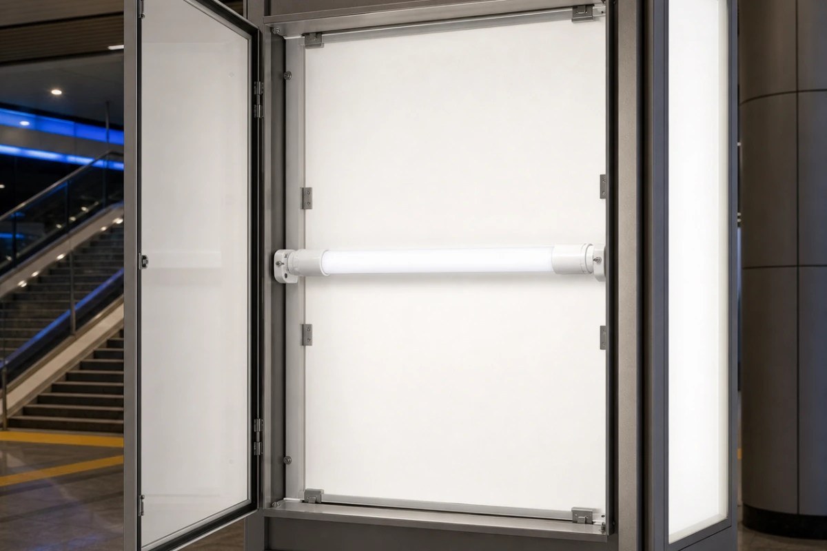
For a double-sided lightbox, measure both faces at agreed points and review the minimum-to-maximum relationship, dark zones around framing, hot spots near the tube and color consistency. For a reflector fixture, compare useful downward and vertical output rather than simply counting rearward lumens.
Use a Worked Example to Identify the Real Bottleneck
Consider two candidate lamps for a double-sided display cabinet. Lamp A has higher bare-lamp efficacy but sends most light toward one face. Lamp B has lower headline efficacy but distributes light around the tube and works with the cabinet reflector to illuminate both faces more evenly.
The correct comparison is not Lamp A watts versus Lamp B watts. Install each exact lamp in the same cabinet, stabilize operation, measure total input power, record luminance or illuminance on both faces, and compare the lowest acceptable point. If Lamp A requires more lamps, a brighter setting or additional diffusion to pass uniformity, its higher bare-lamp efficacy may not produce the lower-energy system.
The same logic can reverse in a one-direction troffer. If rearward output is absorbed, a directional lamp may deliver more useful light per installed watt. Broad emission is therefore an application tool, not a universal upgrade.
Choose the Electrical Retrofit Route Independently
After the optical candidate is identified, determine how the exact model is intended to operate. UL explains that certified retrofit kits include installation instructions identifying suitable host luminaires, major components and required field labels. It also distinguishes Type A/B lamp evaluation as a stand-alone lamp from evaluation as part of a luminaire retrofit kit.
Type A can reduce initial modification when the exact ballast is approved, but the installed result includes ballast losses and compatibility behavior. Type B removes the fluorescent ballast from operation but requires the approved conversion, correct sockets and persistent maintenance labels. Type C uses a matched external driver and has its own system boundaries.
Do not infer a wiring route from the number of luminous surfaces or from whether both lamp ends have pins. Electrical work should follow the exact instructions and applicable local requirements. For step sequencing and safety boundaries, use How to Install LED Tube Lights Safely.
Compare Thermal Behavior in the Actual Enclosure
Double-sided LED placement changes how heat is distributed around the tube. An internal aluminum structure can support heat spreading, but material alone does not establish acceptable operating temperature or lifetime. Drive current, LED-board contact, driver components, end-cap design, enclosure, ambient condition and duty cycle all matter.
Request the rated ambient range and restrictions for enclosed fixtures. Measure temperatures at the points defined by the product or test plan after the representative host reaches stable operation. Repeat the check at the required voltage, control mode and worst credible ambient condition.
Thermal behavior is also an optical issue. Temperature can affect light output and color, while heat-damaged reflectors or diffusers can change distribution over time. A comparison that omits the enclosure may miss the condition most likely to limit the system.
Review Flicker, Power Quality and Controls by Operating Mode
Record flicker using an identified metric and method. Also review power factor, total harmonic distortion, inrush current, surge behavior, audible noise and standby power when relevant. Measurements should identify the ballast, driver, dimmer or sensor and the operating point.
A Type A lamp may behave differently across ballasts on the compatibility list. A dual-mode lamp may have different input power, flicker or control behavior in ballast-operated and line-voltage modes. A tube that operates without visible failure is not necessarily performing as specified.
Do not add dimming, 0–10 V, DALI, wireless, sensing or emergency claims unless the exact product architecture includes them. The dimmable T8 selection guide covers the full control chain separately.
Verify Compliance at the Offered-Model Level
Check the certification database entry, product category, standard, model and suffix, electrical ratings, environmental limitations, factory, installation instructions and current status. Match those details to the physical label and quotation.
UL’s retrofit guidance explains that Type A/B lamps can be investigated to UL 1993 as stand-alone products and additionally to UL 1598C when they form part of a luminaire retrofit kit. A component recognition, a certification logo in a brochure or a report for a neighboring model does not define the offered configuration.
For markets outside North America, build a separate conformity matrix. The LED tube certification requirements guide explains how to map product architecture, market and evidence without treating one certificate as global approval.
Read the Warranty as a Set of Conditions
Warranty length is only one field. Compare the covered model and suffix, start date, operating-hour limit, ambient range, enclosed-fixture restrictions, approved ballast or driver, switching and controls, installation qualification, maintenance duties, lumen or color criteria, exclusions, claim evidence, labor, freight and remedy.
Separate four concepts:
- a product replacement warranty;
- a lumen-maintenance projection;
- a performance specification for the installed system;
- legal and certification compliance.
One does not automatically establish the others. Price uncovered access, labor and downtime in the lifecycle model. A low-cost replacement lamp can become an expensive failure if the sign face must be dismantled or a lift is required for each claim.
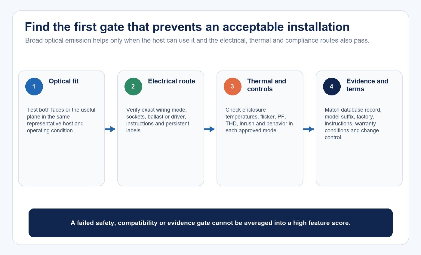
Use a Decision Matrix Instead of a Feature Score
| Gate | Pass evidence | Hold condition | Commercial consequence |
|---|---|---|---|
| Optical fit | Distribution file and representative host test meet the target | Only a 360-degree marketing label is available | Uniformity or glare risk remains unpriced |
| Electrical route | Exact operating mode, ballast/driver, sockets and instructions are identified | Wiring is inferred from the product name | Installation and safety scope is unresolved |
| Thermal fit | Rated limits and representative enclosure temperatures pass | Only heat-sink material is described | Output, driver and lifetime risk remain |
| Compliance | Database record and physical model/label match | Certificate belongs to another model or component | Market-access claim is unsupported |
| Warranty | Written terms cover the intended use and define remedy | Duration is quoted without conditions | Lifecycle comparison is incomplete |
| Change control | Approved lamp, optics, driver and documents are revision-locked | Supplier may substitute without review | Sample approval may not represent production |
Approve the candidate only when the required gates pass. Do not average a failed safety or compatibility gate into a high feature score. Missing evidence should remain visible as missing.
Use the LED lighting sample evaluation checklist to record the exact lamp, host, operating mode and acceptance criteria. For a model-bound comparison, contact New Lights with fixture photographs, ballast or wiring information, lamp-holder details, environment, target distribution and market requirements. The factory and manufacturing page provides context for production and change-control discussions.
Frequently Asked Questions
Does double-sided mean the tube is powered from both ends?
No. Double-sided describes optical emission, while double-ended describes electrical connection. Confirm both independently from the cross-section, markings and installation instructions.
Is a 360-degree T8 tube always more efficient?
No. Bare-lamp efficacy and useful system efficiency are different. The host reflector, diffuser, absorption, geometry and target surfaces determine how much emitted light becomes useful.
Where can broad-emission T8 tubes be useful?
They can be relevant in double-sided lightboxes, display cabinets or other hosts designed to use light around the tube profile. A representative host test should confirm the result.
Can a double-sided tube replace any fluorescent T8?
No. Physical fit, electrical route, ballast or driver, sockets, host condition, environmental limits, installation instructions and compliance scope must all match.
What is the best single comparison test?
Use the exact candidate in a representative host and measure installed power, useful output and distribution while also checking fit, temperature, flicker, controls, labels and model-level compliance evidence.
Editorial Sources
- UL Solutions, “FAQ—UL Certified LED Retrofit Luminaire Conversion Kits”: https://www.ul.com/thecodeauthority/knowledge/faq-ul-certified-led-retrofit-luminaire-conversion-kits
- DesignLights Consortium, “Technical Requirements for LED Lighting: SSL V6.0 & LUNA V2.0”: https://designlights.org/wp-content/uploads/2025/11/SSL-V6-LUNA-V2-TR_final_12082025.pdf
- DesignLights Consortium, “Understanding the Qualified Products List”: https://designlights.org/our-work/solid-state-lighting/understanding-the-qualified-products-list/