


A dimmable T8 LED tube should be selected as part of a complete electrical and control system. The tube, ballast or external driver, control interface, wiring, lamp count, fixture, supply, operating temperature, and installation method must work together.
The word “dimmable” does not prove that a lamp will start at a low setting, dim smoothly, avoid flicker, remain quiet, or operate with an existing ballast and control. Begin with a site survey, choose the retrofit architecture, then qualify the exact product and control chain.
Use the Correct Product Description
T8 describes a nominal tubular form, but it does not fully specify length, base, electrical architecture, input, optics, or controls. Use “T8 LED tube” or “linear replacement lamp” rather than treating every product as an interchangeable bulb.
For each existing installation, record:
- fluorescent lamp designation, length, diameter, and base;
- luminaire manufacturer and model where available;
- lampholder type and condition;
- ballast manufacturer, model, quantity, age, and wiring;
- supply voltage and frequency;
- number of lamps per ballast, fixture, and control channel;
- emergency, sensor, daylight, building-control, or switching functions;
- enclosure, ambient temperature, contamination, and maintenance conditions.
Do not order from dimensions alone. Two tubes that fit mechanically may require different power paths or control equipment.
Choose Type A, Type B, or Type C First
The DesignLights Consortium (DLC) and UL Solutions distinguish linear replacement lamp architectures by how the lamp receives power and by the conversion scope.
Type A lamps operate from an existing fluorescent ballast. This can reduce rewiring, but compatibility depends on the exact ballast and lamp combination. Dimming may depend on the ballast and control connected to it.
Type B lamps operate from line voltage after the fluorescent ballast is removed or bypassed. The wiring arrangement, powered-end configuration, lampholders, markings, and retrofit instructions become critical. The lamp’s integral electronics and supported control method must be defined.
Type C lamps operate from an external LED driver installed as part of the conversion. The tube, driver, wiring, control input, load range, and luminaire conversion must be qualified together.
Dual-mode products may support more than one architecture, but each mode needs its own verified ratings, instructions, dimming behavior, and certification scope. Do not transfer approval from one mode to another.
| Retrofit path | Power arrangement | Dimming dependency | First evidence to request |
|---|---|---|---|
| Type A | Existing fluorescent ballast remains | Exact tube, ballast, lamp count and control combination | Current ballast/control compatibility list |
| Type B | Ballast removed or bypassed; tube receives line power | Integral electronics and supported control method | Certified wiring instructions and dimmer/control list |
| Type C | External LED driver powers the tube | Exact driver, load range, control input and tube | Driver–tube system ratings and conversion instructions |
| Type A+B | Different permitted modes | Separate behavior and certification scope for each mode | Mode-specific ratings, labels, instructions and tests |
The DLC’s current SSL V6.0 requirements include testing and reporting provisions for linear replacement lamps. The program framework does not replace the exact manufacturer compatibility evidence or the installed-system pilot needed for a dimming project.
Map the Complete Dimming Chain
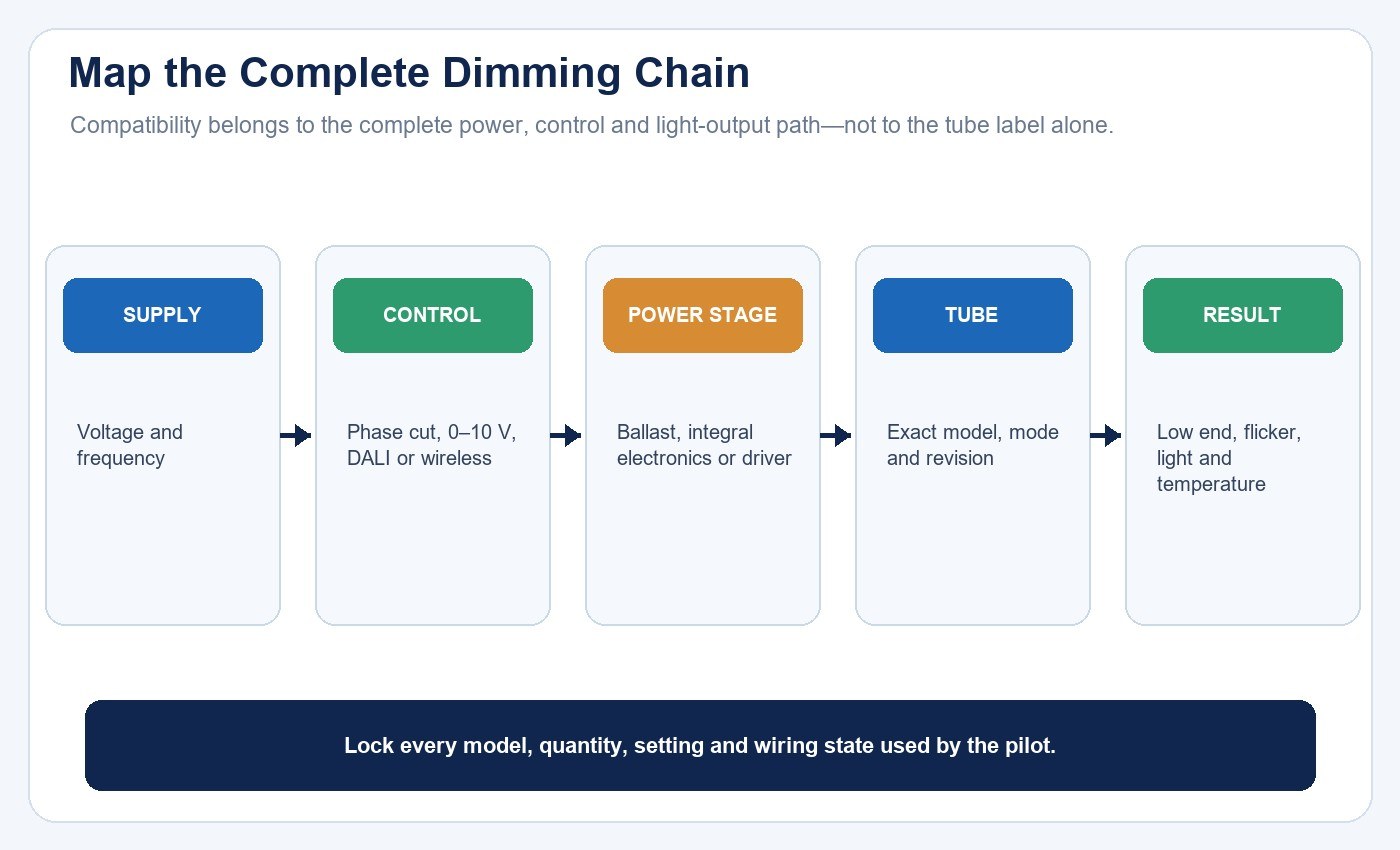
Draw the signal and power path before evaluating products. A project may contain a wall control, lighting-control panel, sensor, gateway, fluorescent dimming ballast, LED driver, line-voltage dimmer, low-voltage control wires, and one or more lamps.
For each component, record manufacturer, model, firmware where applicable, wiring, signal type, load limits, minimum load, maximum device count, and approved combinations. Terms such as phase-cut, 0–10 V, DALI, PWM, or wireless control describe different layers and should not be treated as interchangeable.
A PWM waveform may be generated inside electronics without being an external control interface. A 0–10 V control input may belong to an external driver rather than the tube. Type A dimming can be governed by the existing ballast. Ask exactly where the control signal enters and what device regulates lamp output.
Require a Compatibility List With Conditions
For ballast-compatible Type A products, request a compatibility list that identifies ballast manufacturer, exact model, lamp count, wiring, supply, and supported dimming controls. A family name or “electronic ballast compatible” statement is insufficient.
For phase-cut or other line-voltage control, request dimmer models, channel loading, lamp quantity, wiring, minimum and maximum settings, and test results. For 0–10 V, DALI, or another control method, verify the driver or lamp interface, addressing, curve, standby behavior, control-wire requirements, and failure state.
Compatibility is not permanent if a ballast, driver, dimmer, firmware, or lamp construction changes. Record revision dates and require change notification.
Define Dimming Performance Before Testing
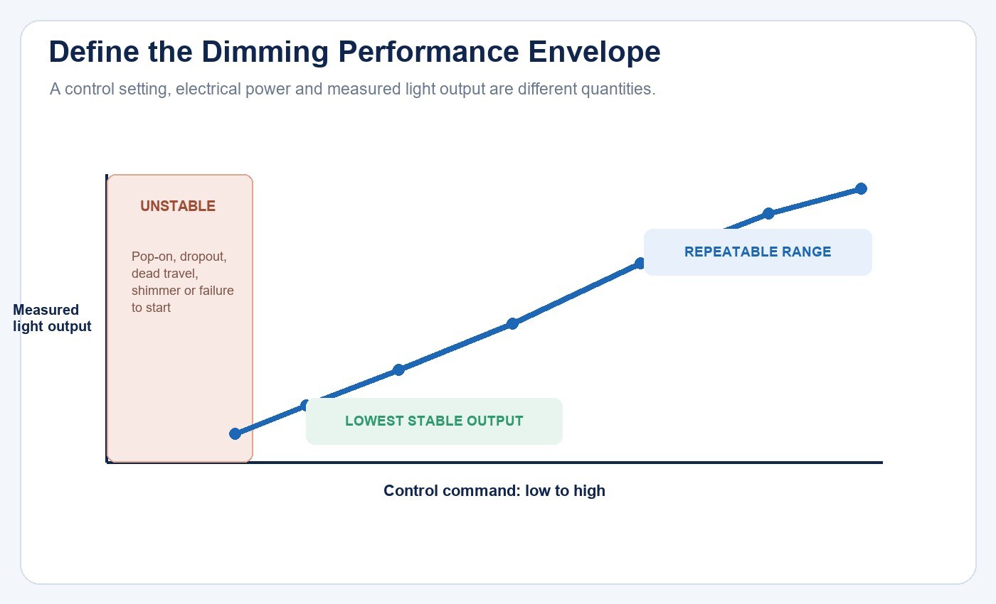
“10–100% dimmable” can refer to a control setting, electrical power, or light output. These are not necessarily equal. Write measurable acceptance criteria for:
- maximum and minimum stable light output;
- dimming curve and repeatability;
- startup at minimum setting;
- pop-on level and dropout level;
- dead travel and hysteresis;
- steps, shimmer, flash, or hunting;
- delay and response time;
- audible noise;
- behavior after an outage;
- multi-lamp synchronization;
- standby power where relevant.
Test from high to low and low to high. Cycle power at several control settings. Repeat with the minimum and maximum planned lamp count and at representative supply and temperature conditions.
Measure Temporal Light Modulation
The U.S. Department of Energy explains that LED drivers and dimmers can interact to create strong light-output modulation. Performance can change with dimming level, driver loading, and the waveform delivered by the control.
Therefore, “no visible flicker” is not a sufficient acceptance test. Capture the optical waveform and report metrics suitable for the project across the dimming range. Include full output, intermediate levels, minimum stable output, startup, and representative abnormal or low-line conditions.
No single TLM metric predicts every visual, stroboscopic, camera, or sensitive-observer response. Define the application and acceptance method in advance. A phone video can reveal an obvious problem but cannot establish compliant TLM performance.
Check Photometrics in the Host Luminaire
Compare delivered light, not only lamp lumens. A replacement tube can have a different beam distribution from the fluorescent lamp, and the existing reflector or lens can change system output and uniformity.
Obtain model-bound reports for input power, lumen output, efficacy, distribution, CCT, chromaticity, and color rendering. Then calculate or measure the host-luminaire result for the project’s task area.
Do not use a universal power-replacement table. A 14 W, 16 W, or 18 W tube does not automatically replace a particular fluorescent system because ballast power, lamp output, optical losses, distribution, depreciation, and project criteria vary.
Likewise, office, school, warehouse, corridor, retail, and healthcare lighting levels should come from the applicable project standard and design, not a generic blog table. Consider uniformity, glare, vertical light, controls, emergency conditions, and maintenance as required.
Verify Color Through the Dimming Range
Specify CCT, chromaticity tolerance, color-rendering criteria, and any project-specific consistency requirement. Do not assign one CCT or CRI value to an occupancy type without checking the design brief and applicable criteria.
Measure or observe whether chromaticity shifts at low output. A product may intentionally warm when dimmed, remain approximately constant, or shift unintentionally. The expected behavior should be stated and verified.
When mixing existing and replacement lamps, compare appearance at multiple dimming levels. Batch and revision control may matter in visually sensitive spaces.
Review Thermal and Enclosure Conditions
LED tube electronics operate inside or near the host luminaire. Enclosed, gasketed, insulated, high-temperature, low-temperature, refrigerated, or contaminated environments can change component temperature and dimming behavior.
Confirm the product’s approved operating and enclosure conditions with model evidence. Review whether the fixture traps heat and whether the dimming ballast or external driver adds loss. Test representative worst-case conditions where the project risk warrants it.
Do not infer reliability from an aluminum housing, a low wattage, or the removal of a ballast. Reliability depends on the complete construction, temperatures, component stress, controls, switching, process consistency, and evidence.
Keep Emergency Lighting Separate
An emergency tube, battery feature, or compatibility claim does not automatically make a converted luminaire suitable as required emergency lighting. UL guidance notes that emergency-lighting equipment has its own certification scope.
Identify whether the existing fixture is part of an emergency system, how it is supplied and tested, what minimum duration and output are required, and whether the complete converted system is certified and documented for that function. Do not mix a normal dimming retrofit with emergency changes without a separate review.
Verify Safety and Certification Scope
Check the exact product category, certificate holder, model, ratings, standards, installation instructions, and certification status. For a retrofit, verify whether the lamp is evaluated only as a standalone replacement or also for the intended luminaire conversion.
UL Solutions has warned about tubes marketed for wiring methods outside their certification scope. This illustrates why labels and instructions must match the approved electrical architecture.
Any ballast bypass, driver installation, lampholder change, control rewiring, or emergency modification should be performed by appropriately qualified personnel under the exact product instructions and applicable requirements.
Run a Representative Pilot
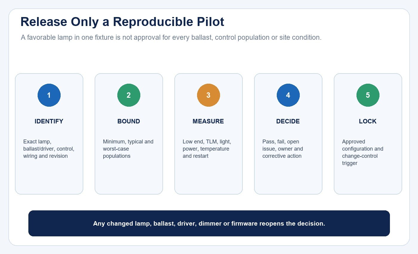
Before a large rollout, test production-representative samples in the actual control chain. Include the most common and highest-risk ballast, dimmer, fixture, supply, lamp-count, and environmental combinations.
Record:
- exact lamp, ballast or driver, dimmer, sensor, and firmware revisions;
- wiring and control settings;
- maximum and minimum output;
- pop-on, dropout, curve, delay, and synchronization;
- TLM measurements at selected levels;
- noise, startup, restart, and switching behavior;
- input power and delivered photometrics;
- thermal observations and operating conditions;
- installation time, markings, and instructions;
- pass, fail, open issue, owner, and corrective action.
Do not approve a whole site from one favorable fixture if several ballast or control populations exist. Either test each defined population or replace it with a standardized architecture covered by the project scope.
A Selection Sequence
- Survey fixtures, ballasts, wiring, controls, supply, environment, and emergency roles.
- Define required light, color, dimming, TLM, energy, safety, and maintenance outcomes.
- Choose Type A, B, C, or a verified dual-mode strategy.
- Obtain model-bound specifications, reports, compatibility lists, certificates, and instructions.
- Build a lamp–ballast/driver–control compatibility matrix.
- Test dim-to-low, startup, dropout, TLM, noise, photometrics, temperature, and restart.
- Approve each existing-system population or a controlled replacement design.
- Lock product, firmware, compatibility-list, and installation revisions.
- Monitor early installations and field returns before full rollout.
Use the commercial LED tube retrofit guide to classify the wider fixture population, then review the driver, dimming and control compatibility guide and LED flicker, PF and THD buyer checklist. The fluorescent replacement solution provides project context. Project teams can contact New Lights with the host fixture, ballast, wiring, control model, lamp count, input, dimming criteria and target market for a model-specific review.
FAQ
Can a dimmable Type A tube work with every fluorescent ballast?
No. Require a model-specific ballast and control compatibility list with lamp count, wiring, input, and test conditions.
Is 0–10 V always the best method?
No universal method is best. Suitability depends on the selected architecture, control system, wiring, behavior, maintenance, and project requirements.
Why does a tube flicker only at low output?
Driver or ballast loading, control waveform, minimum load, regulation limits, and interactions can change across the dimming range. Test the exact combination and measure TLM.
Does a 10% minimum rating mean 10% light output?
Not necessarily. Confirm whether the percentage refers to control input, power, or measured light, and verify pop-on, dropout, stability, and repeatability.
Can a normal dimmable tube be used in an emergency fixture?
Do not assume so. Emergency functions require a separate complete-system and certification review for the intended application.
Is a pilot still needed when the lamp has reports?
Yes for material project risk. Reports do not cover every existing ballast, dimmer, wiring population, host luminaire, control setting, or site condition.
Editorial Sources
- DesignLights Consortium, Technical Requirements for LED Lighting: SSL V6.0 & LUNA V2.0: https://designlights.org/our-work/solid-state-lighting/technical-requirements/
- UL Solutions, LED Certified Retrofit Luminaire Conversion Kit FAQs: https://code-authorities.ul.com/about/blog/led-retrofit-kits-ul-certified-luminaire-retrofit-kit-faqs/
- UL Solutions, New Edition and Scope Expansion of the LED Retrofit Standard: https://www.ul.com/news/new-edition-and-scope-expansion-led-retrofit-standard
- U.S. Department of Energy, Flicker Research: https://www.energy.gov/cmei/ssl/flicker-research
- U.S. Department of Energy, Flicker Basics: https://www.energy.gov/cmei/ssl/flicker-basics












