


A crown reflector changes an LED filament bulb’s light distribution by intercepting part of the light travelling toward the coated area and redirecting some of it into other angles. Depending on the reflector position and geometry, that can reduce direct light through the crown, increase intensity in selected side or lower zones, and change how the lit bulb appears in the fixture.
That change is not automatically an improvement. The useful result depends on socket orientation, filament position, crown geometry, coating, bulb envelope and the surrounding fixture. Total lumens, efficacy, glare and application performance must be evaluated separately. The strongest comparison uses complete-lamp photometric data for the exact models in the intended fixture orientation.
Start With Lumens and Direction as Separate Questions
Lumens describe total luminous flux. They do not show where the light goes. The Illuminating Engineering Society defines luminous intensity as luminous flux per unit solid angle in a given direction, expressed in candelas. A reflector primarily changes this directional pattern.
When a filament emits toward the bulb crown, an uncoated envelope allows much of that light to pass through. A reflective crown intercepts part of those rays. Some are redirected, some are absorbed and some still leave through uncoated areas. The result is a new angular distribution rather than extra light created by the reflector.
“More useful light” therefore needs a named zone and application. More light below a pendant may be useful over a table; less light above the pendant may reduce ceiling brightness. In another fixture, upward flux may be part of the intended ambient effect.
Follow the Light Path Through the Complete Bulb
The diagram shows the basic mechanism, not a measured beam. On the clear-crown side, rays can leave through a larger part of the envelope. On the reflective-crown side, the coated region blocks direct transmission and redirects a portion toward other angles.
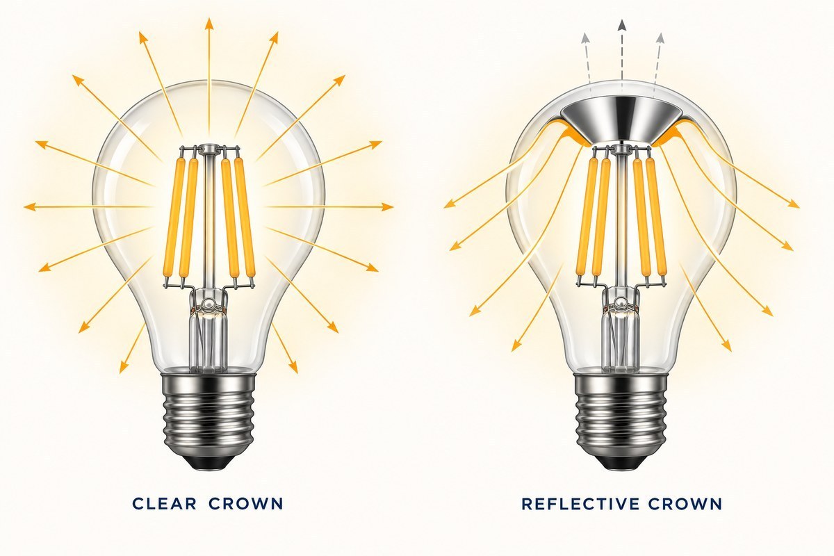
Several interactions determine the final pattern: filament height and orientation, reflector diameter and depth, surface curvature, the distance between filaments and reflector, openings around the crown, envelope shape and refraction, and the cap-up, cap-down or horizontal operating position. A small geometry change can shift peak intensity or create lobes and dark zones.
What the Reflector Surface Can Change
A reflector does not return every incident lumen. Its substrate, coating, roughness, cleanliness, temperature and wavelength response affect how much light is reflected and in what manner. A highly specular surface preserves directional relationships more strongly; a diffuse surface spreads reflected light over more directions. Real finishes can combine both behaviors.
The complete optical path also includes multiple reflections, shadows from filament supports and transmission through the glass. A material reflectance figure cannot be multiplied by lamp lumens to predict application output. It must be connected to the coated area, incident angles and complete-lamp measurement.
The visible crown finish can also be an aesthetic feature. A silver, gold or other mirrored crown changes the unlit and lit appearance of the bulb, even when the project has no directional-performance target.
Read a Polar Plot Before Calling the Distribution Better
DOE guidance on LM-79 reports explains that spatial distribution is characterized by measuring luminous intensity at many angles. Results may be presented as polar plots, intensity tables, zonal lumens, beam or field angles and application plots.
| Photometric item | What it tells you | What it cannot prove alone |
|---|---|---|
| Total lumens | Complete-lamp luminous flux | Direction, glare or task illuminance |
| Polar intensity plot | Candela by angle in one or more planes | The final result inside every fixture |
| Zonal lumens | Flux assigned to defined angular zones | Uniformity on a specific work plane |
| Peak intensity | Highest measured directional intensity | Total output or visual comfort |
| Beam angle | Angular width at 50% of maximum intensity | Spill, dark zones, symmetry or complete spherical distribution |
| Luminance or source image | Apparent source brightness from a stated view | Task illuminance across the room |
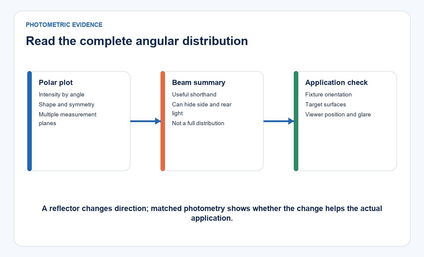
For a nominally symmetric bulb, compare more than one measurement plane before assuming rotational symmetry. Look for peak direction, smooth transitions, unexpected secondary lobes, dark zones and variation among samples.
Beam Angle Is a Partial Description
IES defines beam angle as the angle between the two directions where intensity equals 50% of the maximum in a plane through the nominal beam centerline. For a non-symmetric beam, values may be needed in two perpendicular planes.
This definition depends on the peak. Two products can share a beam angle while differing in peak candela, total lumens, spill, cutoff and distribution outside the 50% points. A broad or multi-lobed filament-bulb pattern may not be well summarized by one beam number.
Do not assign a beam-angle range to an entire crown-reflector product family unless the exact models and measurement planes support it. The shape and crown design can vary across G45, A60, G80, G95 and G125 envelopes.
Efficacy and Application Efficiency Are Not the Same
Lamp efficacy is total lumens divided by input watts under defined test conditions. A reflector can redirect rays and absorb some of them; it cannot create luminous flux. Whether complete-lamp efficacy rises, falls or remains similar must be measured.
Application efficiency asks a different question: does the distribution deliver more of the available light to the target area? That can only be answered with a layout using the same illuminance, uniformity, glare and environmental requirements. If one distribution reduces wasted light in a particular fixture, the project may need fewer watts or lamps, but that is an application result rather than a universal reflector property.
Glare Depends on the Viewer and Fixture
A mirrored crown can block a direct view of some filaments in selected directions. It can also become a bright reflected surface or concentrate intensity toward an observer. The IES definition of glare includes the source’s size, position and luminance, the number of sources and the luminance to which the eyes are adapted.
Evaluate the exact bulb in the intended shade or pendant from realistic standing, seated and circulation viewpoints. Compare products at matched output or state the output difference. A photograph at one exposure can show appearance, but it cannot replace luminance or glare-relevant measurements.
The Fixture Can Reverse the Expected Result
A bare-lamp distribution does not fully predict performance inside a shade, reflector, table lamp or wall sconce. The fixture may intercept the very zone increased by the crown, or it may rely on upward light that the crown suppresses. Socket orientation changes which direction is downward in the room.
For projects involving exposed decorative bulbs, check ceiling brightness, table or shelf illumination, facial modelling, reflections on screens and the visibility of the mirrored crown. The residential and decorative lighting solution provides the wider application context. The article Can LED Filament Bulbs Be Used in Any Light Fixture? covers electrical, thermal and enclosure compatibility before optical preference is considered.
Use New Lights Product Data Within Its Boundary
The current New Lights crown-reflector LED filament bulb family includes G45, A60, G80, G95 and G125 forms, with order references across 2–8 W and 2700–6500 K. Those published fields help define the physical and electrical shortlist; they do not establish one common beam or a guaranteed optical improvement across all variants.
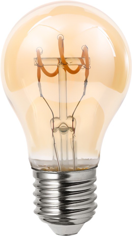
Use the exact model suffix, envelope, wattage, CCT, base and finish when requesting samples or photometry. Buyers can browse the wider LED filament bulb category only after defining the fixture and distribution target.
Compare Exact Models Under Matched Conditions
Use a comparison matrix before accepting an “improved distribution” claim.
| Comparison control | Required record | Why it matters |
|---|---|---|
| Product identity | Exact model, revision, envelope, base and crown finish | Prevents family-level claims from replacing model evidence |
| Electrical condition | Voltage, frequency, input watts, dimming state and stabilization time | Keeps output and efficacy comparisons consistent |
| Photometry | Total lumens, intensity files, polar plots and zonal lumens | Separates redistribution from total-output change |
| Orientation | Cap-up, cap-down or horizontal position | Changes the relationship between crown and target zone |
| Fixture | Shade, socket position, dimensions and surface reflectance | The fixture can block or reuse redistributed light |
| Application result | Illuminance points, uniformity and viewing positions | Connects lamp data to the actual decision |
| Sample basis | Quantity, production lot and test dates | Shows whether the result is repeatable |
If a comparison uses different lumen output, wattage or CCT, record that difference instead of presenting the crown as the only changed variable.
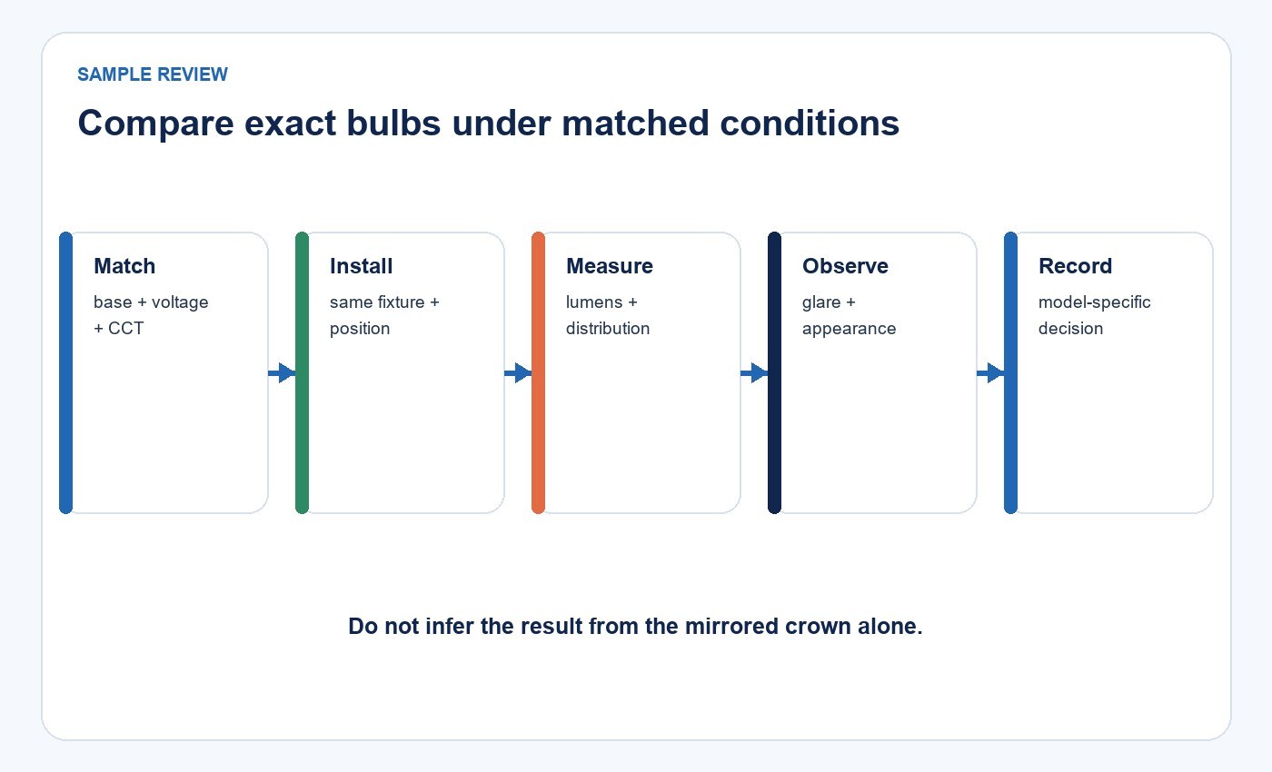
Run a Fixture-Level Sample Review
- Record the fixture, socket orientation, mounting height and target surfaces.
- Identify two exact lamps and confirm their electrical and thermal compatibility.
- Stabilize and measure them under the same supply and ambient conditions.
- Compare input watts, lumens and full intensity data.
- Install each lamp in the intended fixture and measure the same points.
- Observe direct view, reflected glare, ceiling brightness, shadows and appearance.
- Photograph the setup with matched exposure settings for visual records.
- Approve only the exact lamp-and-fixture combination represented by the evidence.
The LED bulb range can support product discovery, but the approval record should preserve the exact model and fixture conditions.
What Buyers Should Request
Request the exact-model specification, dimensional drawing, input data, total lumens, photometric file, polar plots, zonal lumens, CCT and CRI, operating position, dimming compatibility, thermal limits, approvals and warranty terms. If an improvement percentage is claimed, ask for the baseline model, test method and matched conditions.
Also distinguish current test evidence from design descriptions. A section drawing explains geometry; it does not establish the measured output. A coating specification explains material selection; it does not replace complete-lamp photometry. A project photo shows appearance; it does not quantify distribution.
Frequently Asked Questions
Does a crown reflector increase total lumens?
Not necessarily. It redirects some rays and absorbs others. Compare complete-lamp total lumens and input watts for the exact models.
Is a narrower beam always better?
No. A narrower distribution may help a directional task and reduce ambient or upward light. The fixture and target zone determine whether it is useful.
Can beam angle describe the entire bulb distribution?
No. It describes the width at 50% of maximum intensity in a stated plane. Review polar plots, zonal lumens, spill, symmetry and dark zones as well.
Does a mirrored crown guarantee less glare?
No. It may shield direct filament views in some directions or create a bright reflected area in others. Evaluate the installed viewing geometry.
What is the strongest evidence of improved distribution?
A matched complete-lamp photometric comparison followed by calculation and visual evaluation in the intended fixture and space. To review a defined project, contact New Lights with the exact models and fixture details.
Editorial Sources
- Illuminating Engineering Society, “Luminous intensity”
- Illuminating Engineering Society, “Beam angle”
- Illuminating Engineering Society, “Glare”
- U.S. Department of Energy, “Understanding LM-79 Reports”
- U.S. Department of Energy, “Establishing LED Equivalency”
- New Lights, “Crown-Reflector LED Filament Bulbs”












