


A waterproof COB LED strip should be specified and installed as a complete system, not as a roll of tape with one IP label.
The strip body, cut ends, joints, cable entries, profile, controller, power supply and mounting surface each affect water resistance, electrical performance, heat transfer and serviceability. A reliable brief therefore starts with the exposure map and finished assembly, then defines the approved cut-and-seal method, run topology, driver location, access and acceptance checks.
Specify the Complete Strip-Light System
Define the illuminated length, visible light line, viewing distance, channel geometry, bend direction, minimum bend radius, surface material, mounting orientation and access. Record the strip voltage, power per metre, cut interval, conductor arrangement, colour or tunable channels, control method, connector family, profile, diffuser, end treatment, cable type and power-supply enclosure.
Product scope changes the whole brief. A dry indoor media-backlighting product such as a Wi-Fi RGB TV backlight strip addresses a different environment and installation boundary from a sealed architectural run. For room and decorative applications, the residential and decorative lighting solution provides the broader application context, but the project specification still needs the exact system components and exposure conditions.
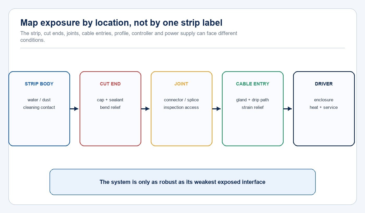
Map Exposure Before Selecting an IP Code
IEC 60529 classifies enclosure protection against access, solid foreign objects and water. That code describes the declared enclosure under its test conditions; it does not automatically describe every site-made transition in a finished strip installation. Identify direct rain, splash, washdown, condensation, standing water, dust, cleaning chemicals, UV exposure, temperature, immersion risk and the direction from which water can arrive.
Map those conditions separately for the strip body, cut ends, joints, connector transitions, cable entries, driver and control enclosure. Also define drainage and drying paths. A horizontally mounted channel can collect water even when individual components appear sealed, while a sheltered vertical run can expose its lower cable entry to runoff.
Build a Continuous Sealed Path
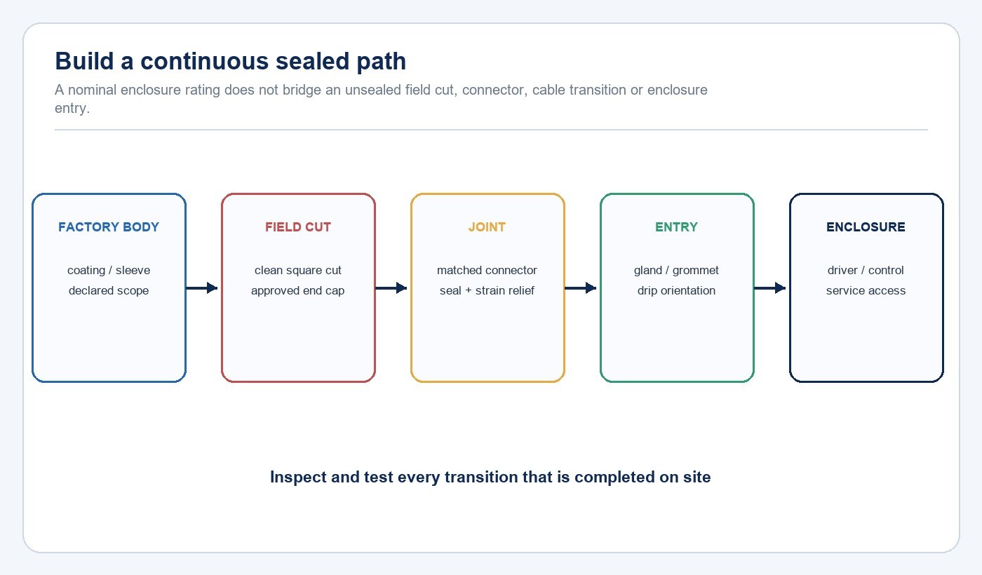
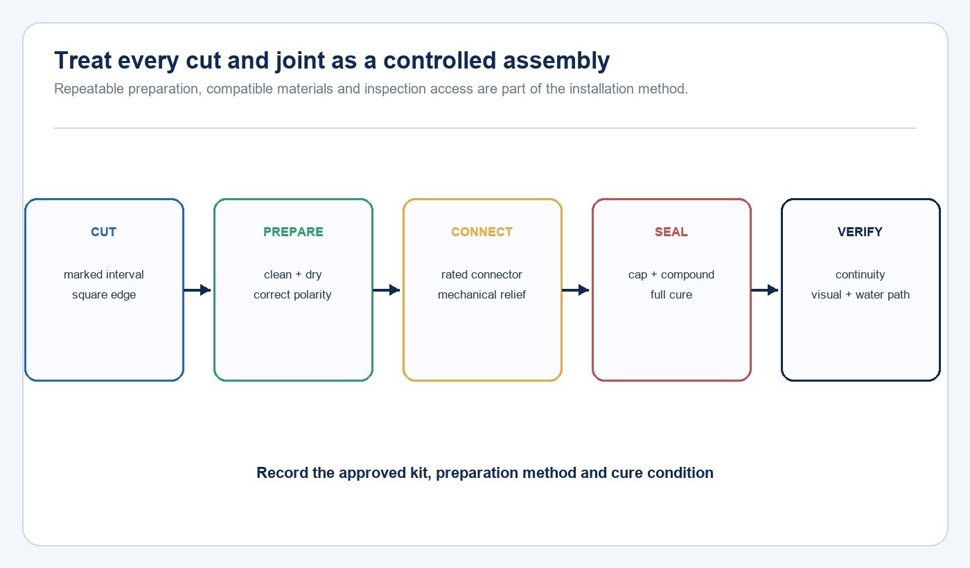
Confirm what the supplier’s declared protection covers: an uncut production length, a factory-fitted lead, a specific connector set, or a fully assembled kit. The field method must preserve that boundary. Specify the approved end cap, connector or solder process, sealant, primer where required, cable gland, strain relief, cure condition and inspection method.
Material compatibility matters. The jacket, encapsulant, adhesive, sealant, profile and cleaning products can interact, and thermal movement can stress a rigid joint. Avoid mixing connector and sealing systems solely because dimensions appear similar. IEC 60598-2-21 addresses rope lights as sealed lighting chains and illustrates why the finished assembly and its supplied construction matter, while the applicable product and market requirements still depend on the actual configuration.
Size Power, Feeds and Controls From the Representative Run
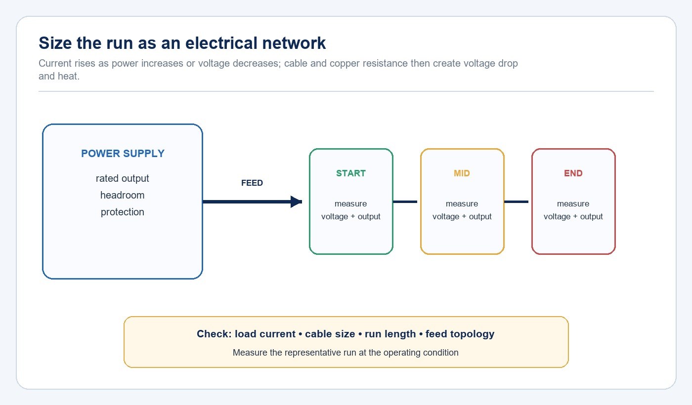
Calculate connected load from the specified power per metre and installed length, then apply the power-supply sizing rules of the selected equipment and project standard. Check output voltage, maximum current, channel count, dimming protocol, minimum load, protection behavior, ambient temperature and enclosure derating. The LED driver and control compatibility guide helps separate electrical compatibility from protocol and commissioning compatibility.
Voltage drop depends on current, conductor resistance, run length, connection resistance and feed topology. A long single-ended run can show lower voltage and visible brightness or colour change toward the far end. Do not approve a length only from nominal watts divided by driver capacity. Measure voltage and visual output at the start, middle and end of a representative run; compare single-end, centre, dual-end or parallel feeds where allowed by the manufacturer.
| Input | What to record | What it controls |
|---|---|---|
| Strip load | Voltage, watts per metre, length and channels | Connected load and current |
| Feed | Cable material, area, length and connection method | Voltage drop and heating |
| Topology | Single, centre, dual or parallel feed | End-of-run performance |
| Driver | Output range, protection, dimming and ambient rating | Electrical and control compatibility |
| Test points | Start, middle and end under operating load | Measured acceptance |
Design the Thermal and Mechanical Path
The mounting surface and profile affect heat transfer, straightness, protection and appearance. Confirm whether the selected strip construction requires an aluminium profile or another documented heat path. Define profile material, dimensions, diffuser, clips, fastener spacing, expansion allowance and how the assembly avoids sharp edges, pinch points and unsupported bends.
Adhesive backing should not be treated as the only mechanical retention where gravity, heat, moisture, texture or cleaning can weaken the bond. Prepare the substrate according to the selected adhesive and profile instructions. Keep driver ventilation and enclosure temperature within the equipment limits, and maintain access for future inspection and replacement.
Control Cuts, Joints and Cable Entries
Allow cuts only at the marked interval and with the tool and method specified for the product. The work instruction should define polarity, conductor preparation, connector insertion or soldering, cleaning, end-cap position, sealant volume, cure time and strain relief. A joint hidden behind a finished surface cannot be inspected or repaired, so place serviceable transitions where they remain accessible.
Route cable entries to reduce water tracking into an enclosure. Use the approved gland or grommet for the actual cable diameter, maintain bend relief and provide a drip path where appropriate. Record the installer, batch, location and inspection result for concealed or repeated joints so a defect can be traced without dismantling an entire run.
Approve a Representative Mockup
Build the mockup with production-intent strip, profile, diffuser, leads, connectors, seals, driver, controller, mounting surface and workmanship. Include the longest or most demanding run, a field cut, a joint, the actual cable entry and the planned service access. The mockup should represent the difficult geometry, not only a short straight sample on a bench.
Inspect the light line for visible dots, dark joints, colour shift, diffuser lines and reflections. Operate all channels and scenes, measure the defined electrical points, check driver and profile condition after stabilization, and apply the agreed water or cleaning exposure method to the finished assembly. Record the acceptance criteria and photographs before the installation method is released. The LED lighting sample evaluation checklist can be adapted to this system-level mockup.
RFQ and Installation Release Checklist
| Package | Required information | Release evidence |
|---|---|---|
| Application | Exposure, geometry, viewing condition, cleaning and access | Marked drawings and exposure map |
| Strip | Voltage, load, cut interval, bend rule, colour and declared protection scope | Datasheet, label and sample identity |
| Interfaces | Ends, joints, leads, glands, sealants and cure method | Approved work instruction |
| Power/control | Driver, feed topology, cable, dimming and protection | Calculation and measured mockup |
| Mounting | Profile, diffuser, clips, substrate and expansion | Section detail and installed sample |
| Quality | Inspection points, test method, batch traceability and repair access | Signed acceptance record |
- Every component and field interface is listed in the RFQ.
- The exposure map covers water direction, cleaning, condensation, drainage and access.
- The declared protection scope is matched to the finished assembly.
- Power, cable and feed topology are checked for the representative run.
- The approved cut, joint, seal and entry method is documented.
- Profile, diffuser, retention and heat path are defined.
- A production-intent mockup passes optical, electrical, control and exposure checks.
- Drawings, instructions and approved files are collected from the New Lights download center or project record.
For component, assembly and production discussions, review the New Lights factory and manufacturing overview. When the marked layout, exposure map and target quantities are ready, send them through the New Lights project enquiry form.
Frequently Asked Questions
Does an IP-rated COB strip make every cut and joint waterproof?
No. The protection of the finished run depends on the declared product scope and the approved treatment of ends, joints, cable entries and enclosures.
How long can one waterproof COB LED strip run be?
There is no universal length. Use the exact strip load, voltage, conductor resistance, feed topology and supplier limit, then verify voltage and light output on the representative run.
Should the driver be installed inside the same wet zone?
Place it only where its enclosure rating, ambient limits, access and wiring method suit the location. A sealed strip does not extend its protection to an unrelated driver or controller.
Is adhesive backing enough to mount a waterproof strip?
Not automatically. Confirm substrate preparation, temperature, moisture, gravity, profile requirements and mechanical retention for the selected construction.
Editorial Sources
- International Electrotechnical Commission — IEC 60529, Degrees of protection provided by enclosures (IP Code): https://webstore.iec.ch/en/publication/2452
- International Electrotechnical Commission — IEC 60598-2-21:2014, Particular requirements — Rope lights: https://webstore.iec.ch/en/publication/2558
- UL Solutions — Lighting Safety Testing and Certification: https://www.ul.com/industries/products-and-components/lighting/lighting-safety-testing-and-certification












