


Select an LED filament bulb driver by starting with the complete bulb requirements—not wattage or a circuit label. The driver must regulate the actual filament string across its voltage and temperature range while meeting the intended mains input, bulb geometry, dimming, temporal light modulation, thermal, EMC, safety and reliability requirements.
This is an OEM engineering and procurement decision. In a self-ballasted filament bulb, the driver is internal mains-connected electronics; the consumer replaces the complete bulb rather than opening it to service the driver.
Start With Requirements, Not a Topology Label
Terms such as linear, capacitive or switching describe parts of an electrical approach. They do not establish that a driver fits a particular bulb. Two candidates with the same nominal wattage can behave differently because their current-regulation range, startup response, losses, component stresses and fault behavior differ.
Freeze the following inputs before comparing candidates:
| Requirement group | What to define | Why it changes the driver decision |
|---|---|---|
| LED load | Filament count, series/parallel arrangement, forward-voltage range, target current and tolerance | Establishes the output compliance range and current-regulation duty |
| Mains input | Rated voltage, allowed range, frequency, brownout, overvoltage and restart behavior | Determines component voltage stress, conversion range and protection needs |
| Bulb construction | Envelope, base, internal volume, insulation system and operating orientation | Limits board size, spacing and heat dissipation |
| Light quality | Output target, ripple, temporal light modulation and color stability | Converts an electrical waveform into visible performance requirements |
| Controls | Dimming method, representative dimmers, minimum level and multi-lamp loading | Changes input waveform, startup and low-load behavior |
| Market evidence | Safety, EMC, surge, power-quality and labeling requirements | Defines the tests and documents needed for the exact construction |
The related guide on what an LED filament is made of explains the light-emitting structure. Driver selection begins where that structure becomes an electrical load.
Match the Output Window to the Actual Filament String
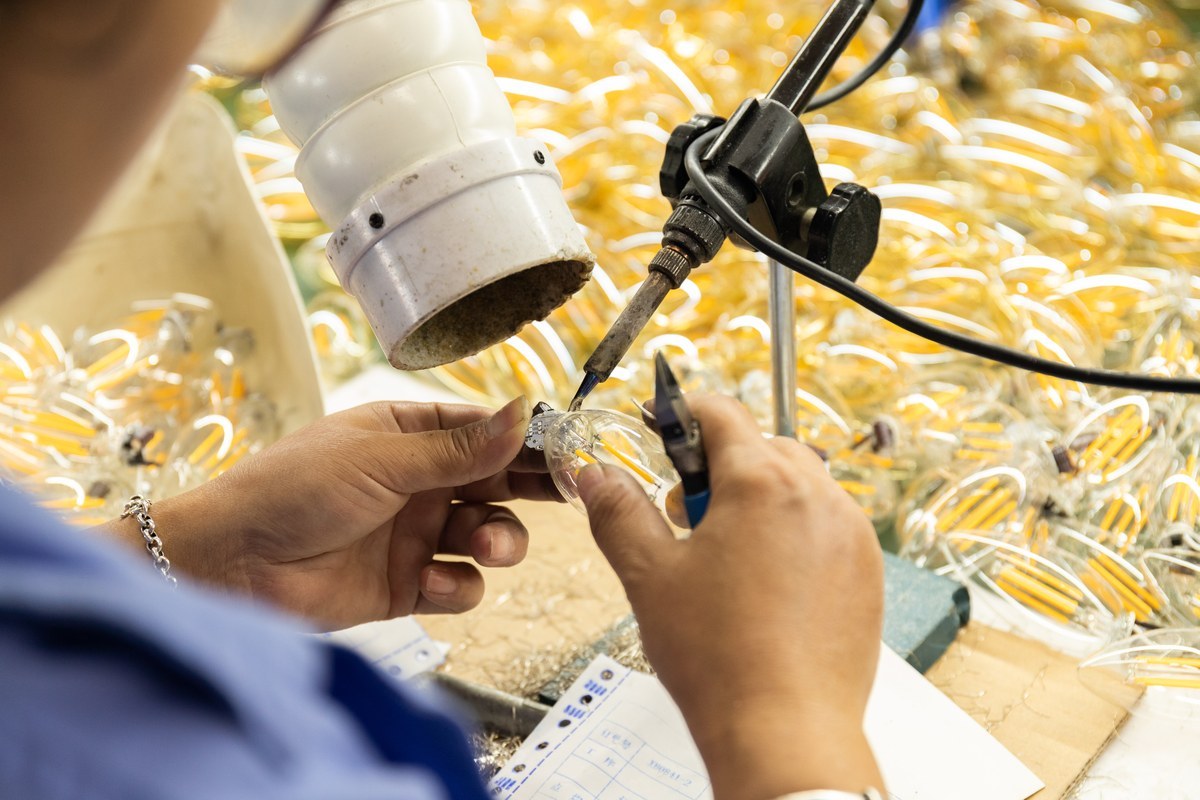
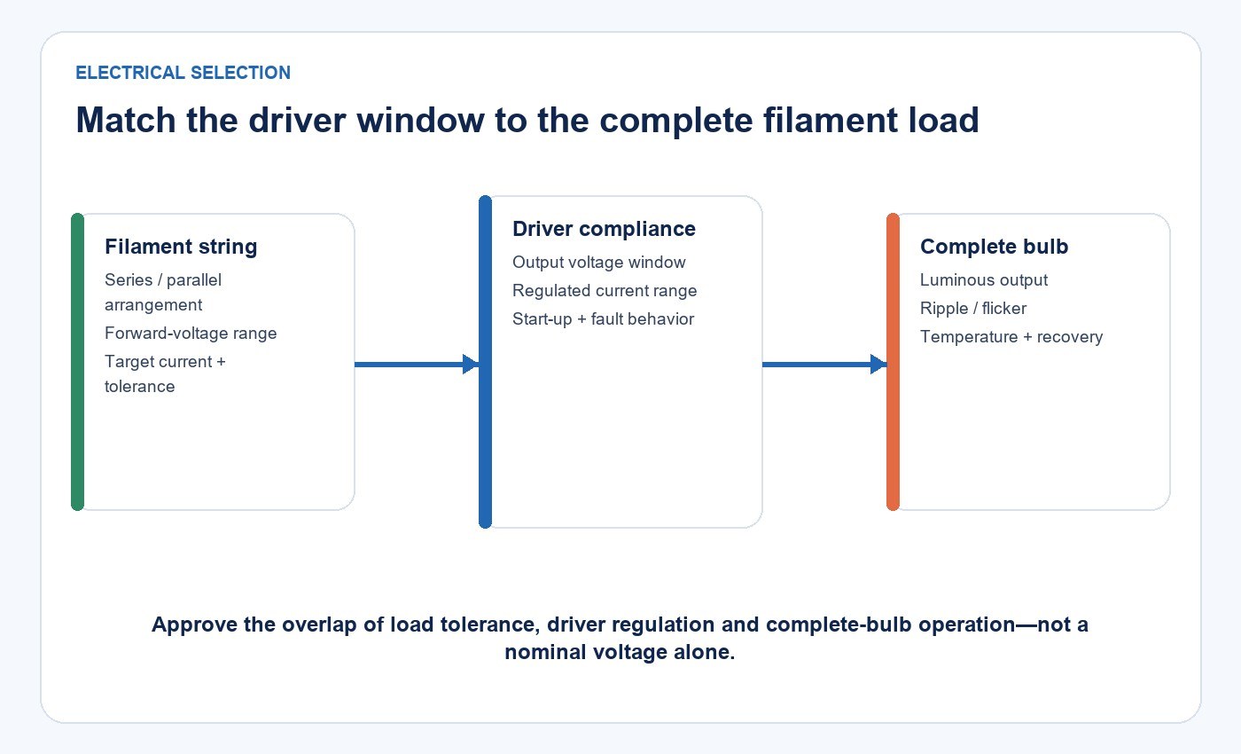
The driver must maintain the specified current while the LED string voltage changes with production tolerance and temperature. A single voltage such as 150 V cannot be treated as a universal filament-bulb value. The usable range depends on chip count, filament construction, wiring arrangement, operating current and temperature.
For each approved string, document:
- minimum, nominal and maximum forward voltage;
- target current and allowable regulation tolerance;
- current sharing between parallel paths;
- startup overshoot and settling time;
- open-string and shorted-string response;
- optical output at the electrical limits;
- behavior at the hottest and coldest qualified conditions.
A driver that regulates correctly at room-temperature nominal voltage may fall out of regulation at a production or temperature extreme. Conversely, excessive compliance voltage can increase stress or loss. The acceptance window therefore needs both load limits and measured driver behavior.
Treat Constant Current as a Performance Requirement
An LED filament needs controlled current, but “constant current” alone is incomplete. Procurement documents should specify the allowed current variation over input, load and temperature, then separately define ripple, startup, fault and recovery behavior.
The U.S. Department of Energy’s LED systems reliability guidance describes power conversion, current regulation, filtering and protection as interacting parts of the lighting system. That system view matters because a bare driver board can meet one bench value while the complete bulb misses a thermal, optical or abnormal-operation requirement.
Make the Isolation and Safety Architecture Explicit
An isolated architecture provides galvanic separation through an appropriate conversion and insulation system. A non-isolated architecture relies on a different complete-product protection strategy. Neither label by itself establishes suitability.
The review should cover accessible parts, creepage and clearance, insulation, cap construction, dielectric strength, abnormal operation and the applicable market standard. The bulb envelope and base are part of that assessment. A lower output current does not make internal circuitry safe for consumer access.
The practical decision boundary is straightforward: choose the architecture that can meet the exact complete-bulb safety requirements within the available electrical, thermal and mechanical envelope. Do not rank architectures as universally obsolete, mainstream or superior without a defined market and evidence set.
Evaluate Power Quality and Light Stability Separately
Input watts, apparent power, power factor, current waveform, harmonic distortion and conversion efficiency answer different questions. Improving one metric can consume board area, component count or thermal headroom, so the specification must identify which limits apply to the product category and target market.
Light stability requires a separate measurement path. The Department of Energy explains that LED driver design and dimmer interaction strongly affect light-output modulation. The Illuminating Engineering Society also notes that percent modulation does not account for waveform shape, duty cycle or modulation frequency. A single “percent flicker” value therefore cannot describe every temporal light modulation outcome.
Capture the light waveform under the required input voltages, temperatures and dimming states. Use the metrics and limits required for the application rather than an uncontrolled phone-camera observation.
Verify Dimming as a Three-Part System
Dimming behavior belongs to the driver, LED load and control together. Specify the control type and representative dimmer models, then check:
- startup at full and low settings;
- minimum stable light level;
- dropout, pop-on, dead travel and hysteresis;
- shimmer, flicker, ghosting and audible noise;
- behavior with one lamp and the intended multi-lamp load;
- restart state after power interruption;
- electrical and thermal behavior at the worst dimming point.
The filament-bulb dimming compatibility guide covers the application-side checks. For a driver approval, repeat those checks on the exact bulb revision rather than transferring a result from another wattage or envelope.
Build an Acceptance Matrix Before Requesting Samples
Use one matrix for every candidate so that a low component price cannot hide missing evidence.
| Verification area | Evidence to request | Complete-bulb check |
|---|---|---|
| Electrical fit | Output-current window, compliance range, startup and fault behavior | Input range, current regulation, optical output and recovery |
| Power quality | Watts, efficiency, PF and harmonic data with test conditions | Repeat at required input and production tolerances |
| Light modulation | Waveform and stated TLM metrics | Measure at full output, low dimming and temperature limits |
| Dimming | Supported control type and tested dimmer list | Check representative dimmers and multi-lamp loading |
| Thermal | Loss estimate, component ratings and derating basis | Map critical component temperatures inside the final envelope |
| EMC and surge | Test setup, applied levels and report scope | Confirm the exact construction and intended market are covered |
| Safety | Insulation system, spacing, abnormal and dielectric evidence | Evaluate the complete self-ballasted lamp |
| Reliability | Component controls, stress limits, switching and life-test plan | Lock revisions and verify representative production samples |
The International Electrotechnical Commission states that IEC 61547:2020 covers EMC immunity requirements for lighting equipment within its scope, including lamps, luminaires and modules. Compliance evidence should identify the exact model, construction, report, standard edition and market; a driver-board report and a complete-bulb report are not interchangeable.
Check the Thermal Envelope in the Finished Bulb
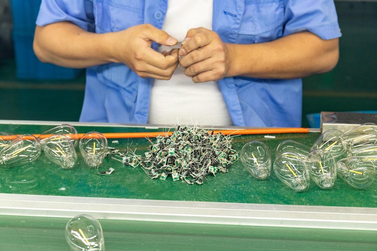
Driver loss becomes heat inside a small base. Envelope shape, board position, nearby filaments, potting, insulation, cap material, orientation and fixture temperature all affect the temperature seen by capacitors, semiconductors, resistors, magnetics, solder joints and insulation.
Measure critical components in the complete bulb at the required input, ambient, orientation and dimming conditions. Compare those temperatures with component ratings and the reliability model. The DOE reliability guidance emphasizes that LED product life is a system result; gradual light depreciation and abrupt electronic failure must be evaluated separately.
This distinction is also important when reviewing filament LED bulb rated life. LED package maintenance data cannot substitute for evidence covering the internal driver and complete lamp.
Control Changes After Approval
A sample approval is only useful if the approved construction remains identifiable. Lock the driver IC, capacitors, magnetics, protection components, PCB, LED filaments, firmware where present, critical materials and assembly process. Require notice and technical review before substitutions.
For each change, identify which electrical, optical, thermal, EMC, safety, dimming and reliability tests may be affected. A physically similar replacement part can change losses, startup, ripple, surge response or temperature. Revision control is therefore part of driver qualification, not an administrative afterthought.
A Practical Qualification Sequence
- Freeze the filament string, bulb envelope, base, target market and control requirements.
- Convert those requirements into output-current, voltage-window, power-quality, TLM, protection, thermal and safety limits.
- Review each candidate’s schematic, isolation architecture, BOM, layout, component ratings and change-control policy.
- Test electrical regulation, startup, faults, watts, PF, harmonics and efficiency across the required range.
- Measure optical output and temporal light modulation at input, load, temperature and dimming limits.
- Complete applicable surge, EMC, dielectric, abnormal-operation and safety evaluations on the final construction.
- Map internal temperatures and connect the results to component stress and reliability assumptions.
- Verify representative production samples, document tolerances and lock the approved revision.
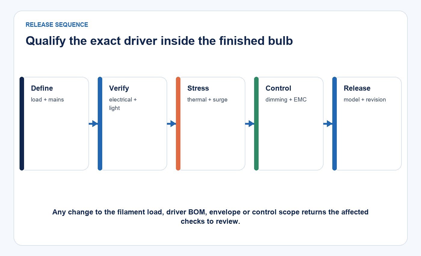
If a candidate cannot provide the evidence needed for one step, record the gap before comparing price. The missing evidence may be more important than a small unit-cost difference.
Frequently Asked Questions
Do all LED filament bulbs use the same driver voltage?
No. The required output window follows the actual filament construction, series and parallel arrangement, operating current, temperature and production tolerance.
Is an isolated driver always the better choice?
Not automatically. Isolation changes the complete safety and mechanical architecture. The correct choice is the one that satisfies the applicable complete-bulb requirements within the available size, thermal and performance constraints.
Can a driver be approved from its data sheet alone?
No. The data sheet supports candidate screening, but final approval requires tests on the exact bulb construction under the intended electrical, thermal and control conditions.
Does a high power factor guarantee low flicker?
No. Power factor describes the relationship between real and apparent input power, while temporal light modulation describes changes in light output over time. Both require their own measurements and acceptance criteria.
Prepare a Bounded Supplier Review
Before requesting a recommendation, provide the filament-string voltage and current range, bulb shape and base, mains market, dimming method, thermal conditions, performance limits and required approvals. New Lights can then review the request against a defined product and evidence scope through the contact page.
Editorial Sources
- U.S. Department of Energy, LED Luminaire Lifetime: Recommendations for Testing and Reporting, Third Edition: https://www.energy.gov/eere/ssl/downloads/led-luminaire-lifetime-recommendations-testing-and-reporting-0
- U.S. Department of Energy, Flicker Basics: https://www.energy.gov/cmei/ssl/flicker-basics
- Illuminating Engineering Society, percent modulation: https://ies.org/definitions/percent-modulation/
- IEC, IEC 61547:2020 — Equipment for general lighting purposes — EMC immunity requirements: https://webstore.iec.ch/en/publication/66774
- New Lights, Filament Bulbs: https://new-lights.com/products/led-bulbs/led-filament-bulbs/












