


Installing an LED panel starts with identifying the panel and ceiling system—not with connecting wires. A lay-in panel for a suspended grid, a recessed panel with a mounting frame, a surface-mounted panel and a cable-suspended panel use different support hardware and leave different amounts of space for the driver and connections.
This guide explains how the four common methods differ and what information should be confirmed before installation. It is a planning guide, not a replacement for the instructions supplied with the selected luminaire. Mains wiring and any work that exposes electrical parts should be completed by personnel qualified under the rules that apply to the project location.
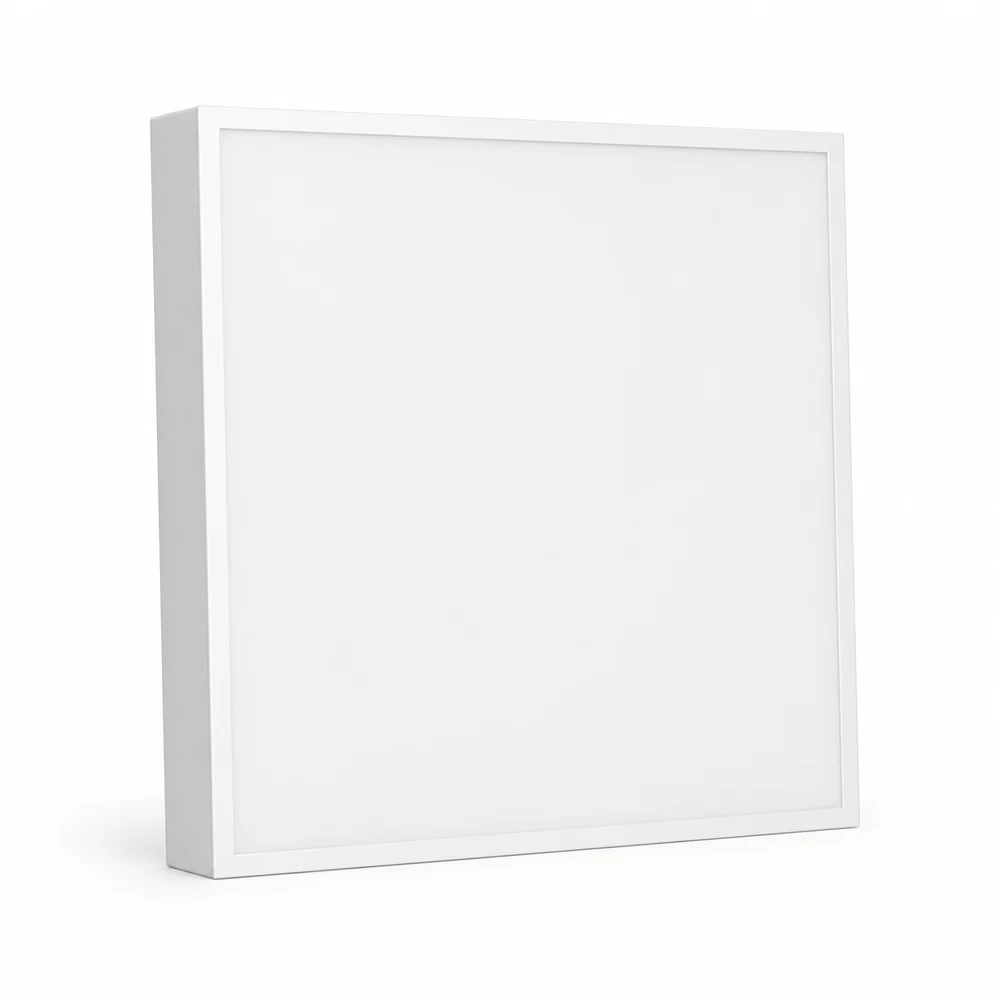
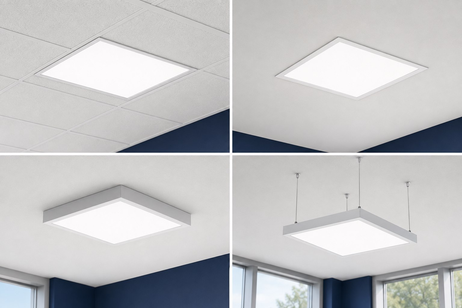
Choose the Mounting Method Before Ordering
The panel, accessory kit and ceiling must be treated as one system. A panel that fits a ceiling opening is not automatically approved for that mounting method, and a surface frame that looks suitable may not provide the correct fixing points, driver space or support.
| Mounting method | Typical ceiling condition | Required product evidence | Main planning risk |
|---|---|---|---|
| Lay-in grid | Compatible suspended T-grid | Panel dimensions, grid compatibility, support and restraint instructions | Assuming nominal panel size equals the actual grid opening |
| Recessed frame or clips | Prepared opening in a hard or suspended ceiling | Cutout, frame or clip kit, clearances and driver access | Cutting before the exact model and kit are confirmed |
| Surface-mounted frame | Solid ceiling without a recess | Approved frame, anchor layout, cable entry and driver space | Using generic hardware or leaving no service access |
| Suspended cables | Open ceiling or design-led suspended installation | Approved suspension kit, fixing points, cable range and safety restraints | Unverified anchors, uneven loading or incompatible attachment points |
If the product documentation does not identify the intended method and hardware, stop and obtain the correct installation information. Do not design a mounting arrangement from appearance alone.
Pre-Installation Information to Collect
Before an installer arrives, assemble a project-specific package containing:
- Exact panel model and dimensions.
- Approved installation method and mounting kit.
- Ceiling construction, opening or grid dimensions and available void depth.
- Panel weight and the manufacturer’s support or restraint requirements.
- Driver type, input voltage and frequency.
- Driver location, ventilation and future service access.
- Dimming or control method, including the required control wiring.
- Circuit and emergency-lighting relationship, where applicable.
- Local electrical, building, seismic and fire requirements.
- The current installation manual for the quoted model and accessories.
These details prevent a common procurement error: selecting the panel first and discovering later that the ceiling needs a different frame, driver location or support method. If the size family is still unresolved, use the LED panel size selection guide before fixing the mounting plan.
Electrical Safety Comes Before Mounting
Turning off a wall switch is not an adequate universal safety procedure. The relevant circuit must be isolated under the site’s electrical safety process, and the absence of voltage must be verified with appropriate test equipment by a qualified person where required.
In US workplaces, OSHA 1910.333 requires live parts to be de-energized before work when employees may be exposed, except under specific conditions. OSHA also explains that an indicator light alone does not verify de-energization. Other countries and project types have their own rules, so the installer must follow the local authority, project specification and product instructions.
Do not energize a panel while wiring is exposed, support hardware is incomplete or the driver and controls have not been checked against the product documentation.
Method 1: Lay-In Installation in a Ceiling Grid
A lay-in panel rests within a compatible suspended ceiling grid. The broad sequence is straightforward, but the details are not universal:
- Confirm the panel’s actual dimensions and approved grid type.
- Verify that the ceiling system and any required independent supports or restraints are ready.
- Plan the driver and connection location so that they remain supported and accessible as required.
- Isolate and verify the circuit under the site’s safety procedure.
- Make the electrical and control connections according to the model instructions.
- Position the panel in the grid without twisting the frame or loading the diffuser.
- Install any required clips, restraints or safety wires.
- Inspect the support and connections before energizing and commissioning.
Do not assume that labels such as 2 × 2 ft, 2 × 4 ft, 600 × 600 mm or 300 × 1200 mm prove interchangeability. Nominal and actual dimensions, grid standards and regional product designs can differ.
Method 2: Recessed Installation With a Frame or Clips
Recessed installation places the panel within a prepared ceiling opening. Depending on the product, the system may use a separate recessed frame, spring clips or another manufacturer-defined bracket.
The exact cutout is a product value. It should be taken from the current drawing for the selected panel and kit—not estimated from the visible face or copied from a similar model.
A practical planning sequence is:
- Confirm the panel, recessed accessory and cutout drawing.
- Check the ceiling material, void depth, obstructions and service access.
- Mark the opening only after verifying the drawing and orientation.
- Prepare the opening and install the approved frame or clips.
- Support the driver and route cables as required by the instructions and local rules.
- Complete the model-specific connections while the circuit is isolated and verified.
- Insert and secure the panel without trapping cables or damaging the ceiling.
- Inspect the fit, support and accessible components before commissioning.
A large panel should not be supported by ceiling board unless the complete mounting system is designed for that use.
Method 3: Surface-Mounted Frame Installation
Surface mounting is used when the ceiling has no suitable recess or grid. A frame fixed below the ceiling creates space for the panel, driver and connections.
The frame must match the panel and provide the intended entry, fixing and closure points. Before drilling, confirm the ceiling substrate, anchor type, cable entry, frame orientation and the space needed to slide or place the panel into the frame.
The general workflow is:
- Set out the frame position and cable entry using the approved drawing.
- Select fixings appropriate to the ceiling construction and verified load requirements.
- Assemble and secure the frame in the sequence given by its manufacturer.
- Isolate and verify the electrical circuit.
- Position and support the driver; complete power and control connections.
- Insert the panel using the frame’s intended opening or removable side.
- Close and secure the frame, checking that no cable is pinched.
- Confirm that the panel is level and retained before energizing.
Avoid generic frames unless their compatibility with the exact panel has been established. Small differences in panel thickness, driver size or fixing location can prevent safe closure or service access.
Method 4: Suspended Cable Installation
Suspended panels hang below the ceiling from a model-specific cable kit. The method can work in open ceilings or where the panel height forms part of the interior design, but it adds structural and leveling requirements.
Before installation, confirm the suspension points on the panel, the number and arrangement of cables, the adjustment range, the ceiling anchors and any separate power-feed arrangement. The building structure—not a decorative ceiling surface—must provide the required support unless the approved design states otherwise.
The planning sequence is:
- Set out the suspension points from the approved drawing.
- Verify the overhead structure and specify suitable anchors.
- Install the ceiling fittings and panel attachment hardware.
- Attach and adjust the suspension cables while the panel is securely supported.
- Confirm that the load is shared as intended and the panel is level.
- Route the power and control cable without transferring unintended load to the conductors.
- Complete the electrical work under the site’s isolation procedure.
- Install required secondary restraints and inspect every attachment before commissioning.
Do not substitute decorative cable, generic hooks or improvised panel holes for an approved suspension system.
Driver and Control Checks
An LED panel may have an external driver, an integrated driver or a product-specific connection box. Some variants are non-dimmable; others may use phase-cut, 0–10 V, DALI or another control method. The panel name alone does not identify the electrical configuration.
Check the exact model for:
- Input voltage and frequency.
- Driver-to-panel connector and polarity where applicable.
- Protective earthing or insulation-class requirements.
- Dimming protocol and control-wire arrangement.
- Driver placement, temperature and access limits.
- Emergency or sensor accessories included in the order.
Never connect a control pair to mains voltage unless the approved wiring diagram explicitly requires it. Do not mix drivers and panels simply because their connectors fit.
Commissioning Before Handover
After the mechanical and electrical work is complete, inspect the installation before energizing. Remove tools and temporary supports, confirm that covers and restraints are secured, and keep people clear during initial energization.
Then check:
- Stable start-up with no flicker, noise or repeated cycling.
- Correct operation of switching and dimming controls.
- Consistent appearance across panels at the same setting.
- Level alignment and even spacing.
- No visible cable pinching, frame distortion or loose hardware.
- Access to drivers or connection boxes that are intended to be serviceable.
- Correct labeling and as-built records for the project.
If a panel behaves unexpectedly, isolate the circuit and investigate the model, driver, control system and connections rather than repeatedly cycling the installation.
Frequently Asked Questions
Can every LED panel be recessed, surface mounted or suspended?
No. Use only the methods and accessories approved for the exact panel. A product may support one method, several methods or require a dedicated version for each.
Can an LED panel replace a fluorescent troffer directly?
Sometimes the opening and grid are compatible, but physical size alone is not enough. Check the support method, circuit, controls, emergency function, driver space and local retrofit requirements.
Does the LED driver need to remain accessible?
Follow the product instructions and local rules. Where the driver or connection enclosure is serviceable, the installation should not unintentionally seal it behind inaccessible construction.
Can a panel be installed on a plasterboard ceiling?
Only with a mounting system and support arrangement suitable for the selected panel and ceiling. Do not assume the board alone can carry the luminaire.
Can I reuse an existing dimmer?
Only after confirming that the panel driver and dimmer or control system are compatible. Dimmable does not mean compatible with every control method.
Who should complete the wiring?
Use personnel qualified for the work under the laws, codes and site rules that apply to the project. This article does not replace electrical training or the model’s installation manual.
Prepare the Installation Package With the RFQ
When requesting an LED panel quotation, include the ceiling type, required panel dimensions, mounting method, supply voltage, control system, emergency requirement and destination market. Link the request to the intended LED panel product family and send unresolved installation questions through the New Lights contact page.
The final installation method should be approved against the quoted model, its accessories and its current instructions before the ceiling is cut or hardware is ordered.












