


LED driver and dimming compatibility is a system result, not a label-matching exercise. Approve the exact supply, controller or dimmer, sensor, gateway, driver, LED load, wiring topology, settings and firmware together. Then test a representative circuit at minimum, typical and maximum connected quantities before releasing the project.
Define the Required Result Before Selecting a Protocol
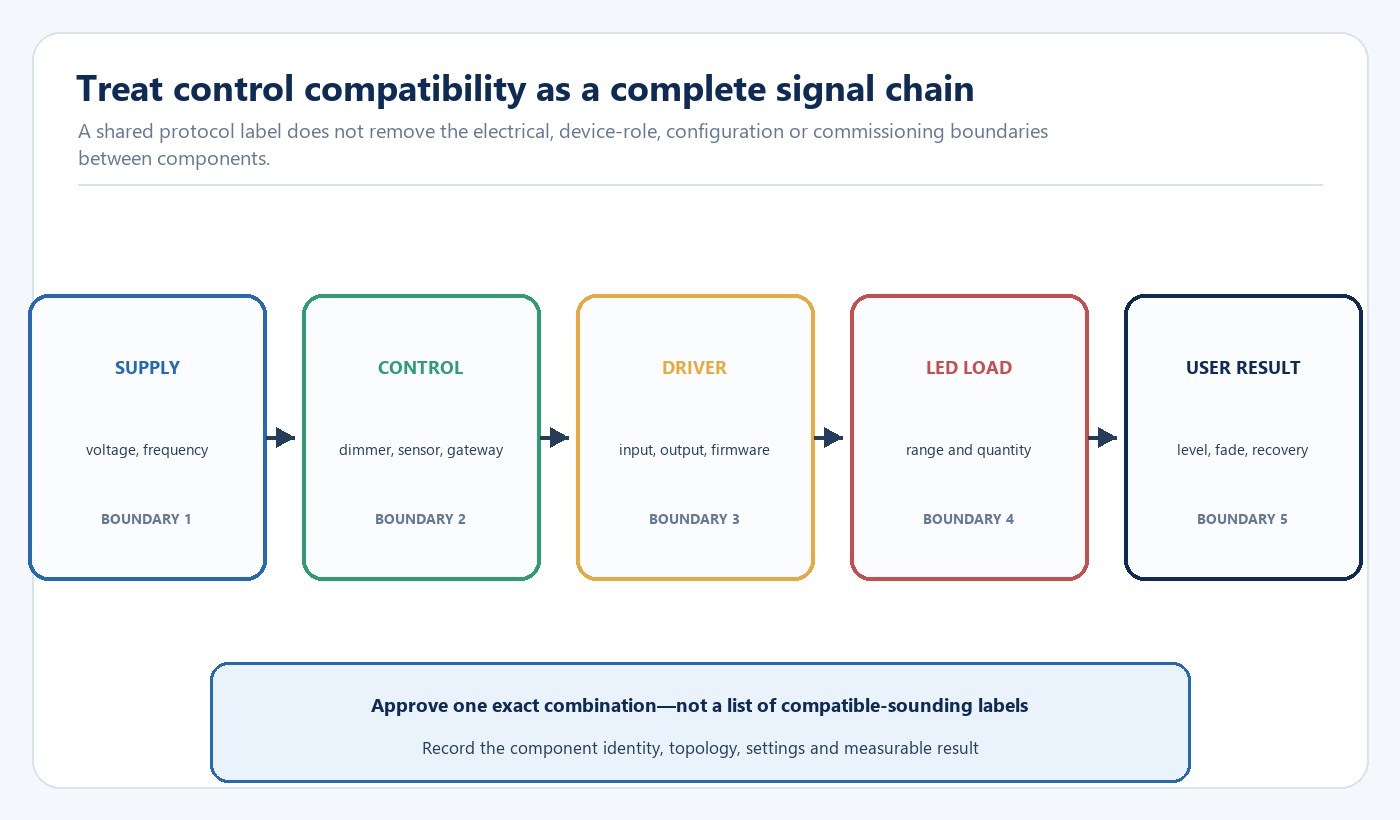
Start with what users and operators need the lighting system to do. Write the required switching behavior, usable dimming range, zones, scenes, fade time, occupancy response, daylight response, schedules, monitoring, manual override, emergency interaction and power-return state. A protocol can transport commands without guaranteeing that the connected luminaire produces the required light level or transition.
Use those functions to select the architecture. The following comparison is a starting point rather than a substitute for device-level approval:
| Architecture | Boundary to define | Representative acceptance test |
|---|---|---|
| Phase-cut | Dimmer type, driver approval, load range and off state | Startup, low-level stability, dropout, noise and full-range transitions |
| 0/1–10 V | Signal range, polarity, sink/source behavior and separate switching | Minimum level, off behavior, multi-driver loading and cable arrangement |
| DALI | Certified device identity, device role, addressing and commissioning tool | Discovery, addressing, groups, scenes, fades, feedback and recovery |
| Wireless or gateway system | Radio/network design, firmware, integration and fallback behavior | Pairing, coverage, command latency, gateway loss, updates and restoration |
The choice should follow the required functions and the building constraints. A simple local dimmer can be appropriate where independent control and limited functions are sufficient. A digital architecture becomes more valuable when the project needs addressing, groups, scenes, status information or repeatable commissioning across many devices. Wireless can reduce new control wiring, but network planning, commissioning access and recovery ownership become part of compatibility.
Map the Electrical, Signal and Configuration Boundaries
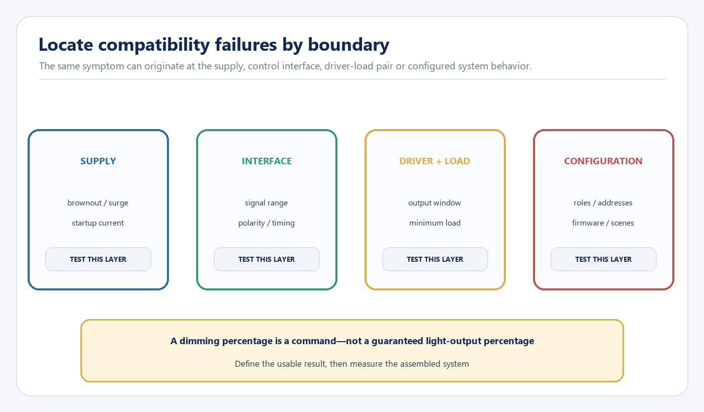
Record the supply voltage, frequency, circuit protection, switching arrangement and any auxiliary power. At the control interface, define the signal type, range, polarity, timing, addressing capacity and expected off behavior. At the driver-load boundary, confirm the driver’s output window against the LED module voltage, current and power across the operating range—not only at full output.
Connected quantity matters. A circuit may behave correctly with one luminaire and fail at the planned quantity because of startup current, dimmer loading, bus power, voltage drop, control-device capacity or gateway limits. Test the smallest and largest expected groups, not only the nominal middle case.
A controller’s 10% command is not automatically 10% measured light output. Drivers can use different dimming curves, minimum levels and cutoff behavior. Define the lowest usable light level, whether the luminaire must switch fully off, acceptable fade smoothness and the permitted startup delay. Measure the assembled system against those targets.
Understand What DALI Certification Does and Does Not Resolve
The DALI Alliance states that DALI-2 certification includes independent verification against the applicable specifications derived from IEC 62386. Its product database identifies certified products by details that can include brand, GTIN, hardware version and firmware version. This makes the database useful for confirming the identity and certification status of the actual device being proposed.
Device roles still matter. The DALI Alliance separates application controllers, which make decisions and send commands, from input devices such as sensors or user interfaces, which provide information. A project therefore needs a device schedule that identifies control gear, application controllers, input devices, bus power supplies, gateways and commissioning tools. A list of products marked “DALI” does not show who supplies bus power, which controller owns the logic or how a third-party gateway handles faults.
Certification narrows one component-level risk; it does not define the project’s groups, scenes, fade times, sensor logic, gateway mappings, emergency interactions or power-recovery behavior. Keep the database identity with the approved bill of materials and test the configured system.
Connect Driver Construction to the Compatibility Review
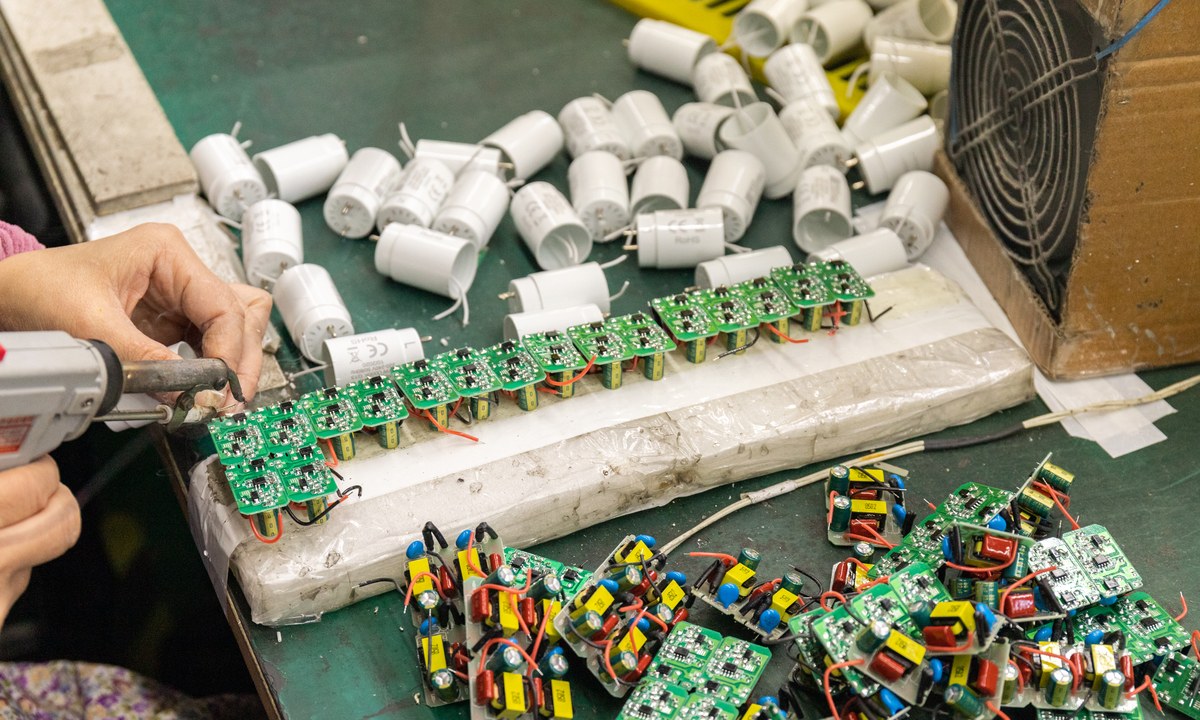
The driver is the electrical and control bridge between the supply and the LED load. Its input stage, control interface, output regulation, protection behavior and firmware determine how it responds to switching and dimming commands. A substitute that fits the enclosure and carries the same protocol can still change startup, minimum level, fade behavior, standby power, audible noise or fault reporting.
For a luminaire project, identify the exact driver model and version, output range, dimming interface, thermal placement and LED load. If the driver is configurable, record the programmed current and any parameter file. If multiple LED boards or channel types are used, document which driver output serves each load. These details belong in the approved configuration, not only in an engineer’s temporary test notes.
New Lights’ product families provide the luminaire context for a compatibility review, while the commercial and retail lighting solutions show how controls relate to application requirements. Model-specific electrical claims should come from the selected product documentation and project schedule.
Build a Representative Circuit and Test Matrix
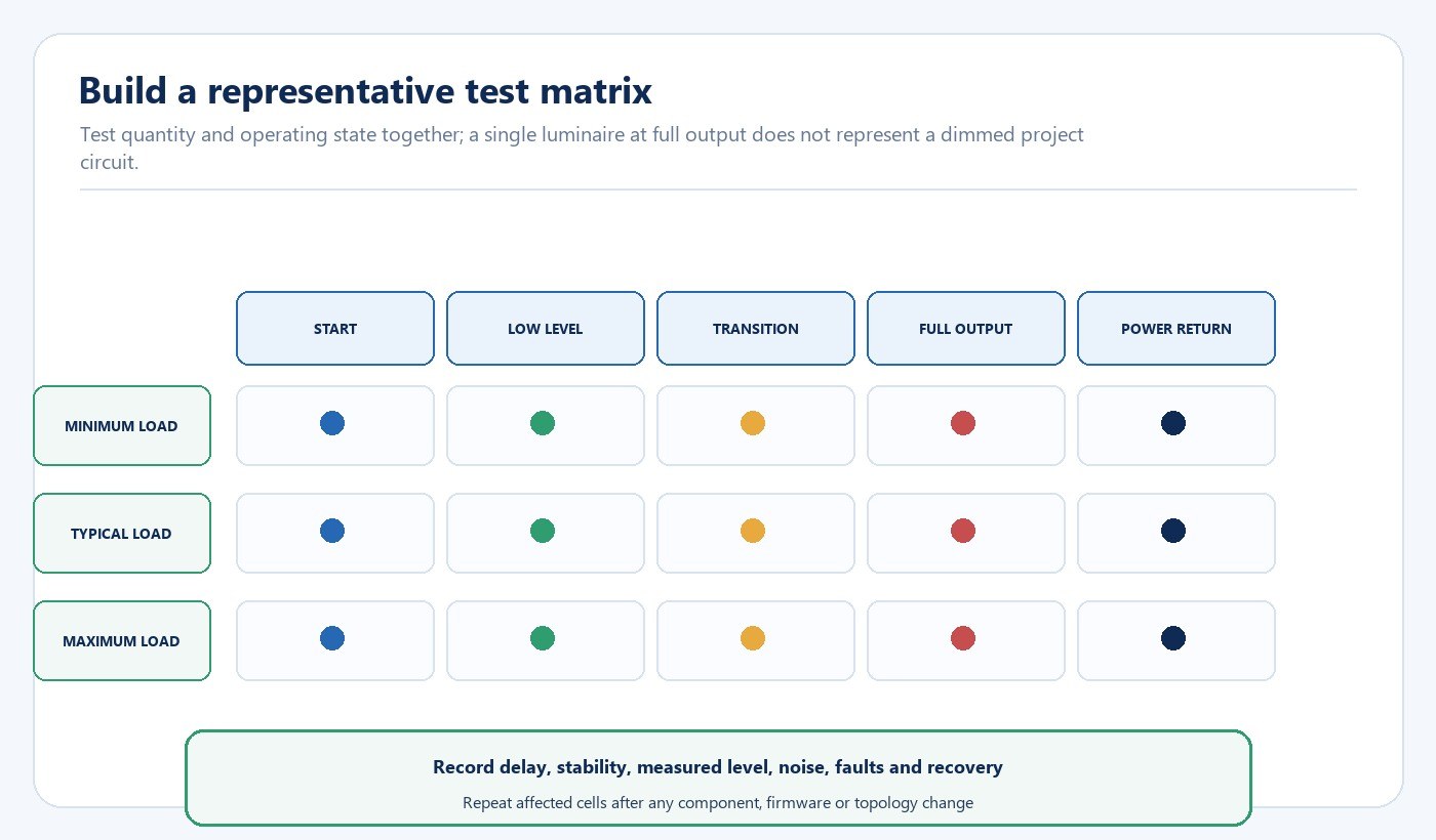
Build the circuit with the intended supply, protection, controller or dimmer, sensors, gateway, driver, LED load and representative cable arrangement. Use production-intent samples with the planned firmware and configuration. Electrical installation and measurements should be performed by qualified personnel under the applicable project rules.
Test at least the minimum, typical and maximum planned connected quantities. For each quantity, move through off, startup, low level, intermediate levels, full output and shutdown. Add rapid commands, long fades and repeated cycles where the user sequence requires them. Record measured light output at agreed points rather than relying only on the controller percentage.
| Test state | Observe or measure | Example acceptance record |
|---|---|---|
| Energization from off | Startup delay, synchronization, flash and protective trips | All units start within the agreed interval without unintended output |
| Minimum usable level | Stability, shimmer, dropout, noise and unit-to-unit consistency | Measured level and visual behavior meet the project target |
| Transition and scene change | Fade smoothness, tracking and command response | No visible steps, stalls or inconsistent endpoints beyond agreed tolerance |
| Full output | Input, driver temperature context and stable light output | Circuit remains stable under the planned maximum load |
| Power interruption and return | Retained state, default state, gateway and sensor recovery | System returns to the defined operating state without manual reconstruction |
| Fault or disconnected device | Reporting, isolation and effect on remaining devices | Fault behavior matches the maintenance and monitoring plan |
Where modulation and electrical quality affect the decision, add the flicker, power factor and THD buyer checklist to the same test plan. The LED lighting sample evaluation checklist can be used to control sample identity, configuration and acceptance evidence before the representative circuit is approved.
Diagnose Common Failure Patterns
When the circuit does not meet the target, change one controlled variable at a time. A failure only at the smallest load points toward a load-range or interface boundary. A failure only at the largest quantity points toward loading, bus power, voltage drop, topology or capacity. A problem confined to one scene or sensor sequence points toward configuration, device roles or gateway logic rather than the LED load alone.
Low-level instability can arise from the control signal, driver implementation, LED load or interaction between them. Startup flash can involve supply sequencing, switching leakage or driver behavior. Audible noise may change with dimming level and mounting. Delayed or inconsistent recovery can come from retained settings, controller startup order, network availability or gateway mappings. The test record should state the condition that triggers the symptom, not simply mark the system “incompatible.”
Camera banding is not identical to human-visible flicker. If the space includes video, machine vision or high-speed imaging, define the camera and operating conditions as part of acceptance. Do not use a phone camera result as the sole acceptance method for every application.
Lock Substitutions, Firmware and Commissioning Records
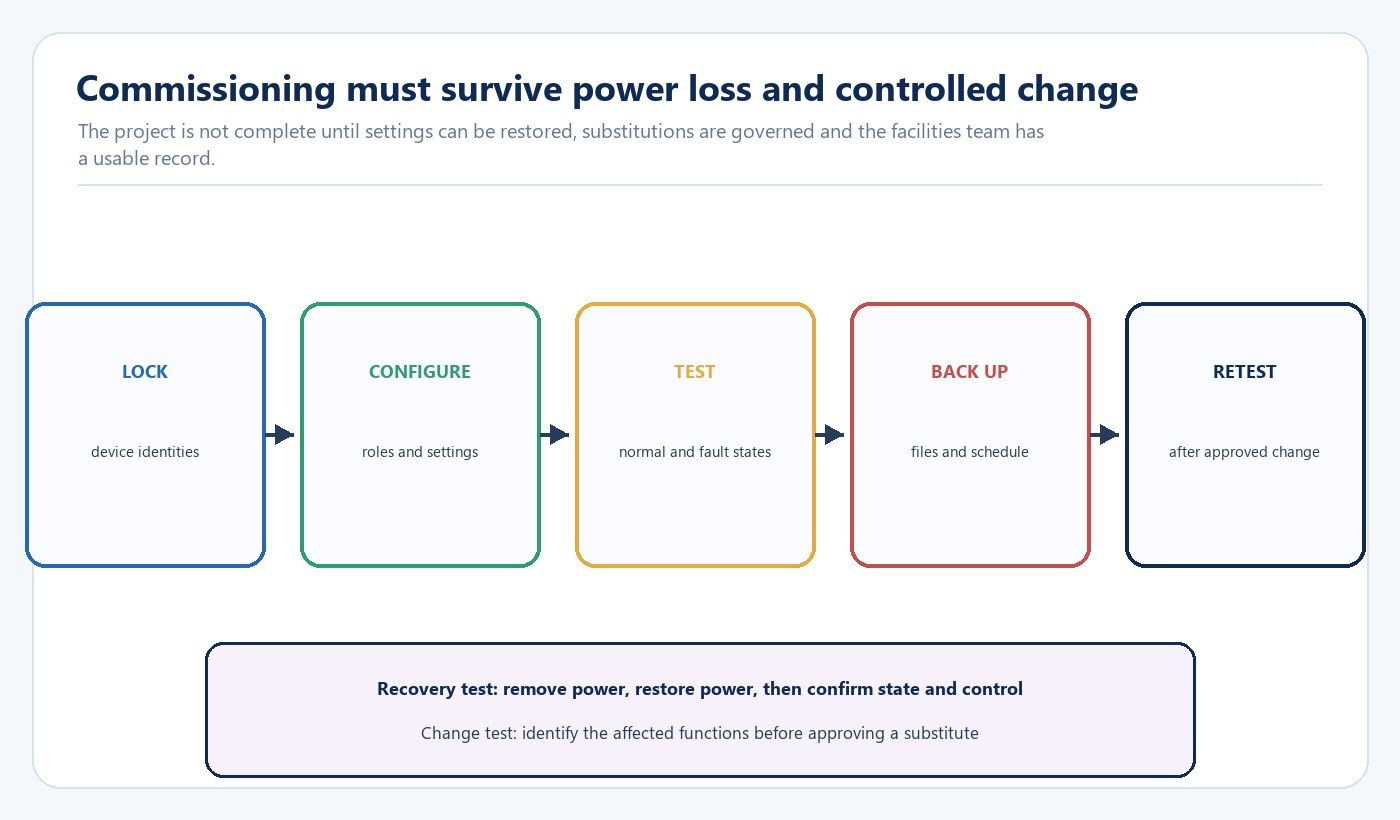
Freeze the driver, controller, sensor and gateway identities before production release. Record hardware and firmware versions, driver settings, device roles, topology, addresses, groups, scenes, schedules and sensor parameters. Save the commissioning file in a controlled project location and give the facilities team a readable device schedule and recovery procedure.
Substitution review should be function-based. Replacing a driver may require repeating startup, minimum level, transition, electrical and fault tests. Replacing a controller or gateway may also require rechecking addressing, scenes, sensor logic, integrations and recovery. A firmware update can change behavior even when the hardware model remains unchanged.
Define who can approve a change, which evidence is required and which cells of the test matrix must be repeated. This prevents an apparently equivalent component from entering production without reproducing the approved user result.
Buyer Release Checklist
- Required user functions and measurable outcomes are written before protocol selection.
- Supply, controller, sensor, gateway, driver and LED load identities are complete.
- Device roles, bus power, topology, addressing and integration ownership are defined.
- Minimum, typical and maximum connected quantities are represented.
- Startup, low level, transitions, full output, faults and power recovery have acceptance criteria.
- DALI certification records match the specific proposed device where applicable.
- Firmware, configuration files and commissioning records are controlled.
- Substitution ownership and re-test scope are agreed before production.
Send the device schedule, required functions, planned quantities and acceptance matrix through the New Lights project enquiry form when requesting a driver-and-control review.
Frequently Asked Questions
Does matching “DALI” on two datasheets prove system compatibility?
No. Confirm the certified identity and role of each applicable device, then test the configured system’s addressing, groups, scenes, transitions, feedback and recovery.
Why can the minimum dimming level change with connected quantity?
The control interface, driver load range, bus or dimmer loading, cable arrangement and device implementation can behave differently at the smallest and largest groups. Test both boundaries against a measured light-level target.
What should be repeated after a driver substitution?
Repeat every function the driver can affect: startup, usable dimming range, transitions, off state, full-load stability, electrical behavior, noise, fault response and power recovery. Record the new driver identity and settings.
Is a successful one-luminaire test enough for a large project?
No. It confirms only that one sample can operate in that condition. Add the minimum, typical and maximum planned quantities and the actual control topology so loading and system interactions are represented.
Editorial Sources
- DALI Alliance, “DALI-2”: https://www.dali-alliance.org/dali2/
- DALI Alliance, “Product Database”: https://api.dali-alliance.org/products
- DALI Alliance, “Control Devices”: https://www.dali-alliance.org/dali/control-devices.html












