A tri-proof light keeps dust and water away from its electrical and optical components only when the complete enclosure works as one system. The cover, base, gasket, clips, end regions, cable entries, fasteners and installation method all affect protection. Temperature changes can also create pressure differences, while trapped humidity can condense on cool internal surfaces.
Evaluate the exact assembled configuration rather than relying on the product name or one component. Map every ingress path, control seal compression, define the cable and mounting conditions, diagnose moisture correctly and test the assembly through the project’s relevant environmental sequence.
Start with the Exact Fixture Construction
Tri-proof families include integrated luminaires and housings for replaceable tubes. The electrical layout, opening method and service boundary are different, so results should remain tied to one complete model and bill of materials.
The current New Lights Integrated SMD LED Tri-Proof Fixture uses an internal light engine and driver behind a PC or PS cover. Its product page lists HIPS, ABS or PC base options, a rubber or silicone sealing ring and a specified cable entry as parts of the documented housing assembly.
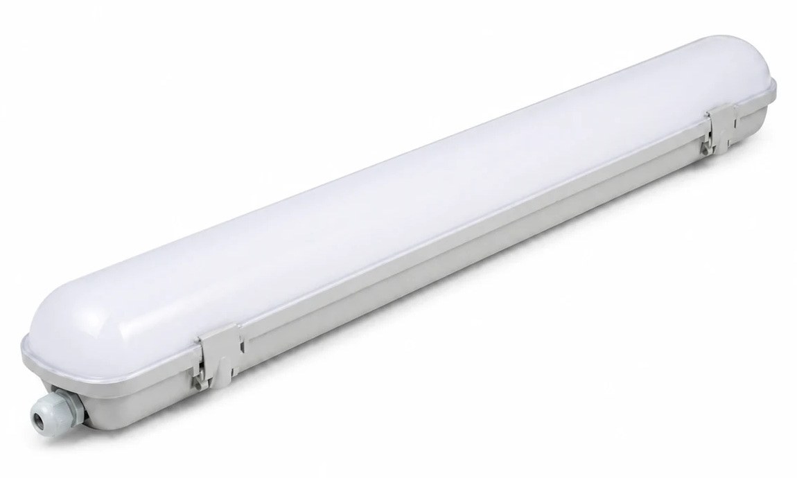
The replaceable-tube tri-proof housing family instead carries G13 lampholders and uses a separately selected tube. Its cover, base, seal, clips, cable entry, tube wiring and service procedure must be reviewed together.
Map Every Potential Ingress Path
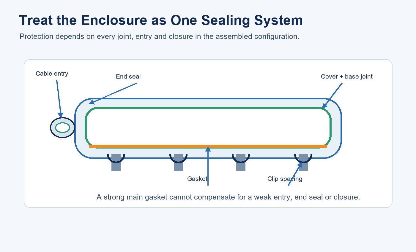
Begin with an assembly drawing and configuration record. Mark the cover-to-base joint, end regions, cable entry, unused entry plugs, connector interfaces, fasteners, mounting penetrations and any opening used for service. A strong main gasket cannot compensate for a loose gland or damaged end closure.
| Potential path | What to define | What to inspect |
|---|---|---|
| Cover and base joint | Seal geometry, mating surfaces and closure method | Continuous gap, distortion, flash and contamination |
| End region | End-cap design, seal and fasteners | Cracks, movement and incomplete seating |
| Cable entry | Gland, cable range, insert, torque and orientation | Cable fit, plug condition and strain relief |
| Clips and fasteners | Type, count, spacing and closure force | Missing parts, uneven engagement and relaxation |
| Service opening | Approved opening and resealing procedure | Gasket damage, twisting, dirt and incorrect reassembly |
If a vent or membrane appears on the drawing, add its body, membrane, bond and protective location to this map. Do not assume that a sealed-looking plug is a pressure-equalization device.
Control Gasket Material and Compression
A gasket must maintain contact around the full perimeter. Too little compression can leave a capillary path; excessive compression can deform the seal, overstress clips or reduce recovery after opening. Material name alone does not define performance.
Record cross-section, hardness, length tolerance, joint method, compression target and compatibility with the cover and base. Inspect molding variation, sink marks, burrs, scratches and local bowing. Long linear housings deserve special attention because small dimensional changes can accumulate along the joint.
| Seal variable | Low-control failure | Production control |
|---|---|---|
| Cross-section and hardness | Uneven contact or excessive closure force | Approved drawing, material code and incoming check |
| Gasket length and joint | Stretching, gaps or overlap | Controlled cut/join method and visual standard |
| Mating surfaces | Local channels from dirt, flash or distortion | Cleaning and surface inspection |
| Compression | Under-sealing or permanent deformation | Defined closure gap, force or fixture method |
| Reopening | Twisted, contaminated or aged seal | Service inspection and replacement criteria |
The gasket should be controlled as a production component, not as an interchangeable strip selected only by color or nominal material.
Use Clips to Distribute Closure Force
Clips translate enclosure geometry into gasket compression. Their material, spacing, engagement and retention affect whether the joint closes consistently from end to end. Plastic and stainless-steel options should not be treated as mechanically identical without configuration evidence.
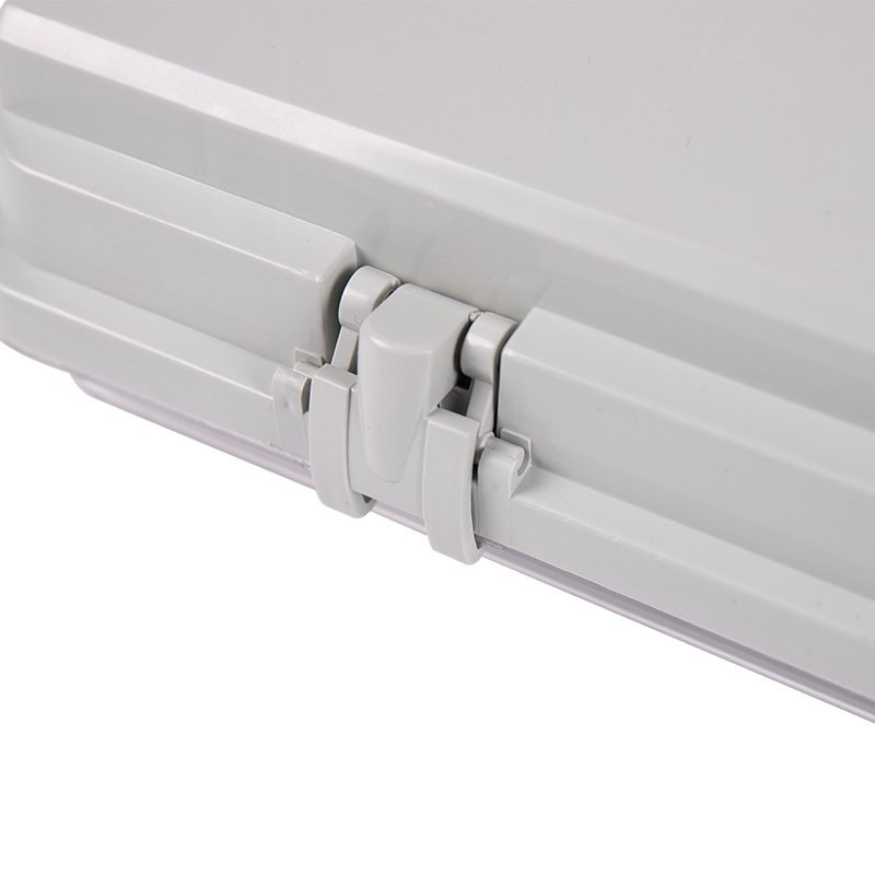
The current TW, TL and TS replaceable-tube housings list plastic or stainless-steel side clips, metallic mounting clamps and rubber or silicone sealing rings depending on the selected series. Preserve the exact clip count and type in the model record and test sample.
Specify Cable Entries and Field Wiring
The cable, gland and enclosure wall form another sealing system. Define the approved cable outside-diameter range, gland or connector reference, seal insert, locknut, tightening method and strain relief. An entry sized for one cable may not seal a smaller, flattened or damaged cable.
Where loop-through wiring is allowed, specify both entries and the treatment of unused ports. State whether entry orientation matters under the intended exposure. Field drilling, substitute glands and loose plugs can invalidate the tested assembly even when the main enclosure remains unchanged.
Installation instructions should also identify the internal wiring boundary and required qualified electrical work. The outdoor lighting installation checklist provides a wider framework for supply, mounting, cable routing and commissioning decisions.
Understand Pressure Changes Without Inventing a Vent
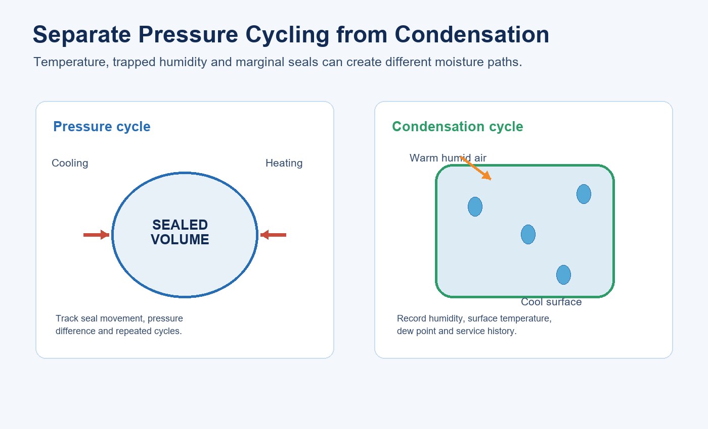
Air inside an enclosure expands as temperature rises and contracts as it cools. Repeated operating and weather cycles can apply alternating pressure across gaskets and entries. Cooling can encourage air and moisture movement through a marginal joint.
A selected pressure-equalization membrane can allow gas exchange while resisting liquid water within its specified conditions. It also adds design variables: airflow capacity, membrane area, location, attachment method, contamination, chemical exposure and service damage.
Current New Lights tri-proof product pages reviewed for this article identify gasket, clip, base, cover and cable-entry configurations; they do not list a vent membrane or pressure-balance valve. If a custom design introduces one, place its exact part number, drawing location and assembly method in the bill of materials and include it in validation.
Separate Pressure Cycling from Condensation
Water droplets inside a luminaire do not identify their source by appearance alone. External liquid may have crossed a weak joint, humid air may have entered during service or assembly, or trapped moisture may have condensed when an internal surface fell below the dew point.
| Observation | Possible mechanism | Evidence to collect | Avoid concluding |
|---|---|---|---|
| Droplets after cool-down | Internal air reached dew point | Humidity, air and surface temperature, timing | The main gasket leaked |
| Moisture near cable entry | Entry path or condensation at a cool interface | Entry condition, cable fit and local temperature | Every perimeter seal failed |
| Repeated moisture after washing | Direct ingress, retained water or service damage | Exposure direction, cleaning method and seal inspection | A vent alone will solve it |
| Moisture after opening | Trapped humidity or incorrect resealing | Service record, gasket condition and reassembly | The original factory assembly was unchanged |
Inspect the outside before opening the enclosure, document moisture location and preserve the sequence of events. Opening too early can move droplets, release pressure and disturb the seal condition needed for diagnosis.
Interpret an IP Rating at the Assembly Level
IEC 60529 defines degrees of protection provided by enclosures. An IP code belongs to a tested configuration and procedure. The applicable report should identify the model, materials, seal, cable entry, mounting condition and sample arrangement.
IP65 should not be expanded into immersion suitability, condensation prevention, chemical resistance or permission for every high-pressure cleaning process. Those exposures require their own project definitions and evidence. The IP ratings guide for LED lighting explains how the digits separate solids and water protection.
Request the report scope and compare it with the quotation, sample and production bill of materials. If an OEM option changes the cover, base, seal, clips, entry or fasteners, review whether the previous result still applies.
Add Environmental Conditioning Before Retesting
A single ingress test may not reveal seal movement, clip relaxation or material distortion caused by service cycles. Build a sequence around the actual installation: temperature extremes, operating heat, cool-down, humidity, cleaning exposure, vibration or UV where relevant.
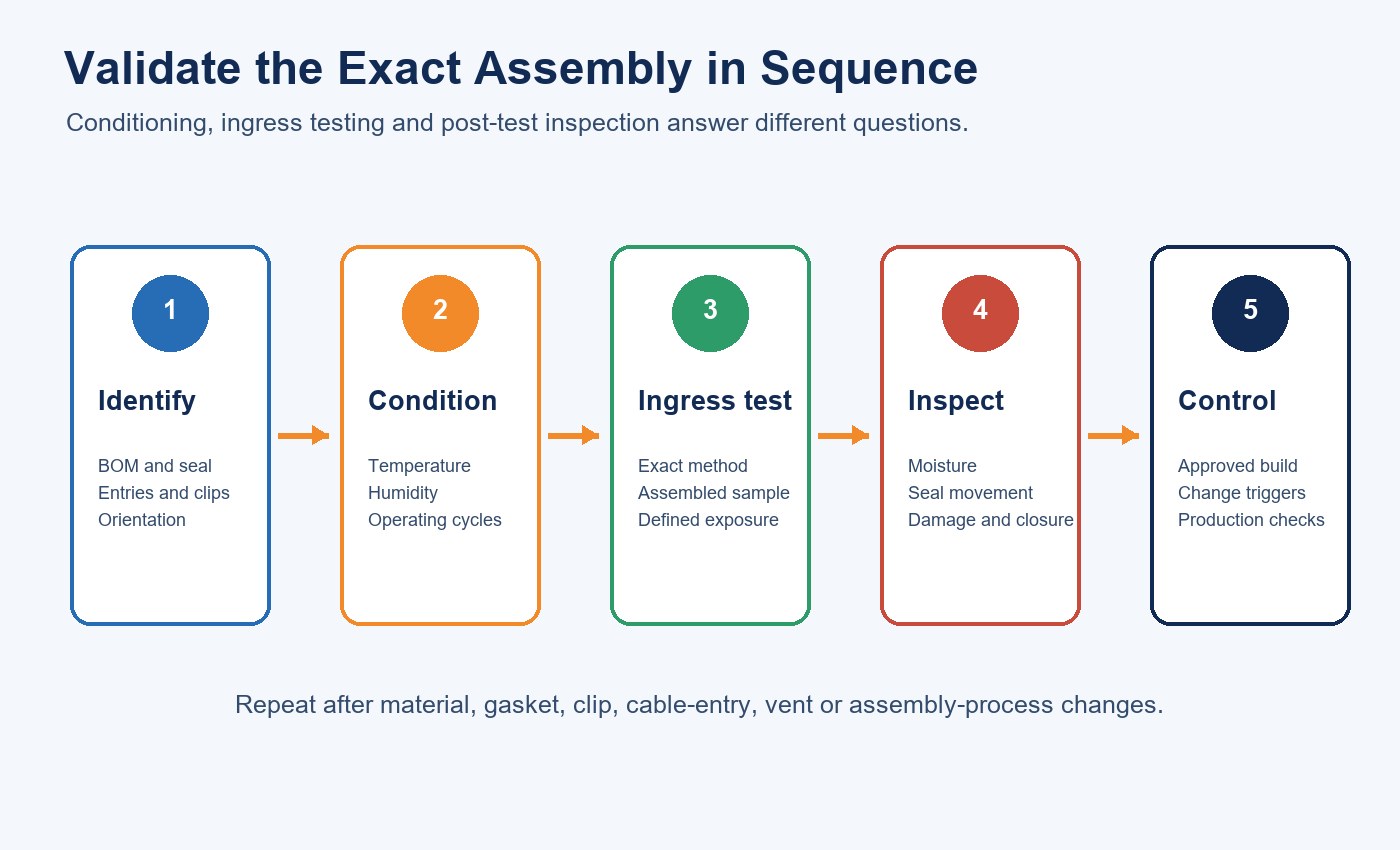
Define the cycle range, rate, dwell, operating state and number of cycles. Inspect the seal before and after conditioning, then repeat the applicable ingress method when the project requires aged performance. An arbitrary internal-pressure test should not be labeled as an IP test unless it follows the relevant defined method.
Build a Configuration-Controlled Validation Record
The LED lighting sample evaluation checklist can be extended with enclosure-specific evidence. Retain sample IDs, photographs, drawings, bill of materials, assembly settings, conditioning records, ingress results and post-test inspection.
| Stage | Required record | Release question |
|---|---|---|
| Configuration | Model, materials, gasket, clips, entry and orientation | Is the sample identical to the offered build? |
| Assembly | Surface condition, closure method and inspection | Was the enclosure assembled consistently? |
| Conditioning | Environment, cycle profile and operating state | Does it represent the project exposure? |
| Ingress test | Method, sample state and observations | Did the exact assembly meet the defined classification? |
| Change control | Approved references and retest triggers | Will production remain equivalent to the sample? |
Supplier controls should verify the correct gasket and entry, clean mating surfaces, clip count and closure, along with any specified leak or end-of-line check. The lighting supplier factory audit checklist helps place those controls in a wider manufacturing review.
Preserve Sealing Through Installation and Maintenance
Transport damage, incorrect mounting, substitute cables and rushed servicing can change the enclosure after factory inspection. Define mounting orientation, bracket spacing, cable routing, gland tightening, restrictions on drilling and the process for reopening and resealing.
Maintenance records should identify when the enclosure was opened, what parts were replaced and whether the gasket was cleaned, inspected or renewed. Use the lighting maintenance and spare-parts planning guide to keep approved seals, clips, glands and housings tied to the installed model.
For warehouse projects, the warehouse lighting RFQ checklist adds layout, controls, access and operating conditions to the enclosure decision.
Prepare the Supplier Brief
Provide the target market, installation location, dust and water exposure, cleaning method, temperature and humidity range, mounting orientation, cable and entry requirement, service frequency and required IP classification. Ask for the exact model configuration, applicable report and change-control process.
The New Lights factory and manufacturing capability page outlines the wider production context. To review an integrated or replaceable-tube tri-proof configuration, contact New Lights with the enclosure and installation brief.
Frequently Asked Questions
Does the term tri-proof guarantee IP65?
No. Check the exact assembled model and the scope of its applicable report. Product names and family-level options do not replace configuration evidence.
Does IP65 prevent condensation?
No. Condensation also depends on trapped humidity, surface temperature, thermal cycles and service history.
Must a sealed light use a pressure-equalization vent?
No. Some designs rely on controlled sealing; others add a selected membrane. Confirm the actual component from the drawing and bill of materials.
Can a gasket alone determine the IP rating?
No. Gasket geometry and compression interact with mating surfaces, clips, end regions, cable entries and assembly quality.
Can an IP65 light be immersed or pressure-washed?
Do not infer those exposures from IP65 alone. Define immersion or cleaning conditions separately and request evidence that covers them.
When should ingress testing be repeated?
Review retesting after changes to materials, gasket, clips, cable entry, vent, fasteners, dimensions, assembly process or relevant environmental conditioning.